The fins are there only to increase the surface area to achieve the above objective. No my point is, how does it matter in what way the fins are oriented (i.e. Horizontal or Vertical)
capt
i beg to differ- it matters - it mattera a whole LOT
as you have said heat in amps is mostly achived through radiation
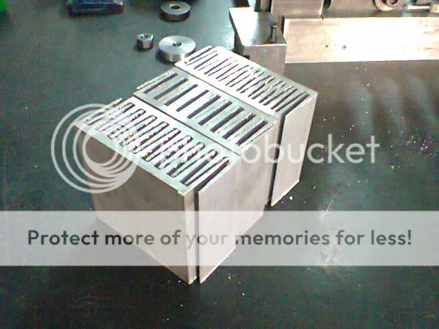
the above orientation allows less heat to be transferred this way
the top most fin blocks all hot air moving upwards
(actaully each fin does this for the fin below it)
Furthermore if you allign horizonatally only one side of each fin is actaully contributes ( to a comparitive extent) to radiation ( if any )
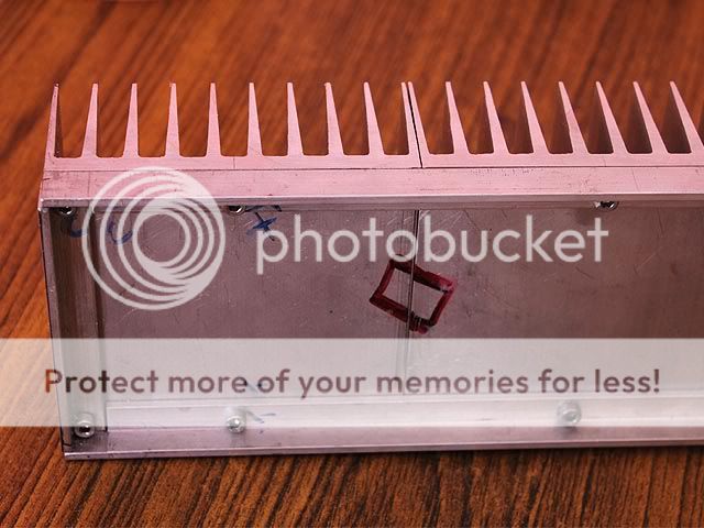
other than that the surface area of the same sink alligned with fins vertically offer far more surfacce area ( provided cut pieces are use side by side)
your sink could well be down to only 20% of its true efficiency
this is only a lay explanation
the technical explanation is long - google it
please check the orientation of heatsink fins on most commercial / pro amps
hell even on active subwoofers
Also check any of the DIY amps On DIYA audio
leaving out a few amps that have horizonatally alligned fins ( and theres an explanation for that too) all amps will have vertically alligned fins only
if the above orinetation worked well people would never have to break their head about sourcing WIDE extrusions
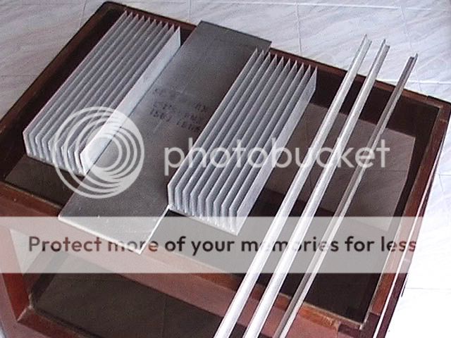
A 4 inch wide ( as used above would serve all purposes when cut to diffrent lengths)
see
here for amateur builds
Chip Amp Photo Gallery - diyAudio
Post your Solid State pics here. - Page 3 - diyAudio
for pro/commercial amps just visit their websites
Anyway
this is derailing the thread
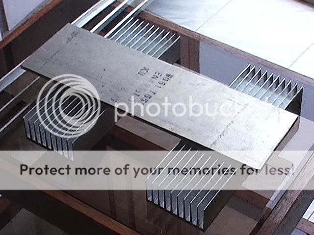
all i wanted to say was this is not correct orientation of sinks
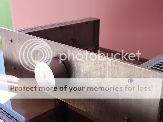
however it should work in the OP's case since the sink is major overkill so he does not have to worry about efficiency
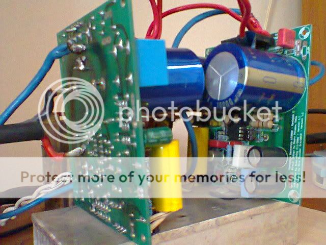
this orientation (IMO) is being used for aesthetics ( so the heatsink forms the side walls of the cabinet) and the build looks cool
The build could have very well be completed by using a sink slightly larger than what capt had posted earlier and installing it INSIDE the cab too(fins vertical only)


 hyeah: