It does not matter to me if it's a HE or SHE, what matter to me is wether HE or SHE knows to make a "Power Cable".Tut, tut, tut
How do you know it's a HE? And not a SHE?
Not to forget the rainbow colours that are available too!
You are using an out of date browser. It may not display this or other websites correctly.
You should upgrade or use an alternative browser.
You should upgrade or use an alternative browser.
Finally my DIY tube amp project gets kick-started
- Thread starter Hari Iyer
- Start date
Well done Hari, looking forward to further impressions...Finally from today evening the monoblocks are playing in stereo.
Thanks Susnick, the Hammonds 159z takes around 200hrs for break-in and the tubes around 70 hrs. Capacitors will take another 300hrs and around 50hrs to 60hrs for the wires and solders. Will post my listening impression post that. Also my stock OPT will need to be replaced by Softone after a while when they are available. Till then stay tuned.Well done Hari, looking forward to further impressions...
Cheers,


yogitashwer
Member
All the best for the project.
Last week and this made some interesting discoveries concerning power supply topology in tubes and how much they affect overall tone of an amplifier. It makes me wonder that how much we discuss about power cables and it's impact which could be either minute or huge without giving much thought about how good are the amplifie's power supply is actually designed. What I want to say is don't pour money changing power cables if your amplifier's and other components of your gear's power supply is just basic. Only if you have a well designed power stage in your amplifier will any change in cable will actually matter ( if at all).
In this DIT tuve amplifier I have used 2 chokes each in my power stage in an LCLC arrangement and they cost almost 10k for four numbers. But the correct tonality and dynamic range came from replacing the 2 chokes with an 200 watts incandescent lamp and I have now changed the confirmation to RCRCRC ( Where R is an incandescent lamp of 100, 200, 200 watts each). Total cost just 100/- for both channels . Almost 100 times lower than using chokes. I have now listened for a week and posting after that. I also did a simulation with PSUD2 why the lamps sound better than the chokes to my ears and discovered that there is a rectifier pulse noise using chokes which is not present in the bulbs. Also the current drawn by the load (amplifier) during the draw cycle is pulsed and noisy and also not in-phase with the voltage with chokes, but with bulbs it's clean DC draw not pulsed and in-phase with voltage. All this simulation made me wonder how much time and money we spend on power cables, where the solution could lie somewhere else which could be very cheaper and better.
Now with this topology I can't now say it's same as originally designed by Jeff, but a modified version of his design.
Thanks for looking.
After countless discussion and testing I removed the bulbs and now they are back to original design. Have added an hash choke just after the transformer center tap which is under testing. May decide later if that need to be retained or go.
Yesterday added bypass capacitors (24 of them in both monoblock) and vacuumed the amplifier to remove all solder / plastic debris. Now only two final changes are pending - replace the top wooden plate to brass and change the OPT. Both these will have to wait couple of months. Till then just relax and enjoy the music
Thanks for looking.
Where did you manage to buy incandescent bulbs? Please could you share the source?Last week and this made some interesting discoveries concerning power supply topology in tubes and how much they affect overall tone of an amplifier. It makes me wonder that how much we discuss about power cables and it's impact which could be either minute or huge without giving much thought about how good are the amplifie's power supply is actually designed. What I want to say is don't pour money changing power cables if your amplifier's and other components of your gear's power supply is just basic. Only if you have a well designed power stage in your amplifier will any change in cable will actually matter ( if at all).
In this DIT tuve amplifier I have used 2 chokes each in my power stage in an LCLC arrangement and they cost almost 10k for four numbers. But the correct tonality and dynamic range came from replacing the 2 chokes with an 200 watts incandescent lamp and I have now changed the confirmation to RCRCRC ( Where R is an incandescent lamp of 100, 200, 200 watts each). Total cost just 100/- for both channels . Almost 100 times lower than using chokes. I have now listened for a week and posting after that. I also did a simulation with PSUD2 why the lamps sound better than the chokes to my ears and discovered that there is a rectifier pulse noise using chokes which is not present in the bulbs. Also the current drawn by the load (amplifier) during the draw cycle is pulsed and noisy and also not in-phase with the voltage with chokes, but with bulbs it's clean DC draw not pulsed and in-phase with voltage. All this simulation made me wonder how much time and money we spend on power cables, where the solution could lie somewhere else which could be very cheaper and better.
Now with this topology I can't now say it's same as originally designed by Jeff, but a modified version of his design.
Thanks for looking.
IndianEars
Well-Known Member
Great to know that you have removed the incandescent bulbs. They are extremely non linear and yield very very poor Power Supply regulation. They probably introduced huge distortion as the volume is cranked up or with dynamic music.
Series bulbs are great as a Self Protection circuit, when testing an amplifier for first switch on, or during repairing.
If used as a permanent circuit element, they will create a non linear "lamplifier".
Incandesent bulbs have been used as series elements in Public Address speakers to prevent them from damage. Bise used them in their pro audio (not domestic audio) speakers.
Several decades ago, BEVOX (Bajaj Electronics) used them as emitter resistors in their solid state amps, creating their 'lamplifier'.
Almost never used today except during testing.
Thanks @IndianEars for your perspective. I agree the incandescent is non-linear and a peak current limiter. They helped me to realise few things about my amplifier. How much DCR is affecting dynamics, how good an RC filter helps to filter ripple and how they can Rob music of its transients. I won't put this as a futile exercise in my learnings. I believe DIY is all about discovering the magic sound that you have dreamt about. If I can't try various combinations and permutations of component choice and various design ideas then there is no point in going DIY and just building as per original design which most of DIYers do. Imo, each one of us hears differently and if you cannot tailor the sound to your taste then DIY is waste. For that you need a good understanding of what you are looking for and what tweaks work or don't work for you. It's better to have a design that's scalable over time.
Now the amplifier is back to the original design and have completed around 250+ hours of break-in and they sound quite refined after the burn-in without harshness or over energitic. Did some modifications on the preamplifier internal wiring which had an influence on the overall sound presentation. I am not planning any more mods to this amplifier other than replacing the OPT and the top cover and I am done.
Now the amplifier is back to the original design and have completed around 250+ hours of break-in and they sound quite refined after the burn-in without harshness or over energitic. Did some modifications on the preamplifier internal wiring which had an influence on the overall sound presentation. I am not planning any more mods to this amplifier other than replacing the OPT and the top cover and I am done.
Next week I shall be trying some bare solid silver wire 97% purity with pin hole gold plating for my preamplifier internal wiring (thanks to FM @yogibear for sending this wire to me). My current 26 awg X 2 silver plated copper wire is already very mellow and neutral. Let me check if the solid silver wire can better them.
I have tried various internal wiring wires like solid copper, stranded copper, solid silver plated copper, tin plated copper and none of them could match with my monoblocks for transparency and neutrality.
I have tried various internal wiring wires like solid copper, stranded copper, solid silver plated copper, tin plated copper and none of them could match with my monoblocks for transparency and neutrality.
It seems the Softone OPT is not going to be available for a long time due to supply chain disruption aftermath of Covid 19. I have been searching for other options agressively and may mostly settle with a orient super HiB double c core type OPT. They are a bit more expensive than Softone and Hoshimoto but again I don't have an option as of now. I have waited for this for over 4 months now, but I am unable to see light at the end of the tunnel. Imo, EMS India is using Covid 19 as a business strategy and are avoiding any imports. Almost 90% of countries have resumed EMS airfreight other than few like India and US.
Hari,
Does any friend on this Forum know of people who travel back and forth, India to Japan and back, so they can personally help to get you a pair of Softone RW-20s???
Does any friend on this Forum know of people who travel back and forth, India to Japan and back, so they can personally help to get you a pair of Softone RW-20s???
Good suggestion Jeff, but most corporate offices have not resumed international travel ( including mine) and that will continue for atleast 6 more months if my guess is correct. If anyone traveling to Japan and back read this post - please contact me.Hari,
Does any friend on this Forum know of people who travel back and forth, India to Japan and back, so they can personally help to get you a pair of Softone RW-20s???
Thanks,
I received my POSHAN OPT today which was ordered last month. The build quality of this transformer is excellent. The DCR measured is 250 ohms.
My measured speaker impedance is 2.5 ohms in the linear range and increases from 1khz onwards to 6 ohms at 20 kHz. The impedance being low the reflected primary impedance will be lower if I use the suggested taps. So I need to measure the voltage to get the correct tap to use for my amplifier with my speaker load.
I required 30VAC at the primary to get 1VAC at the first secondary tap. So my turns ratio is 30:1 for the first secondary tap. Hence the square of impedance ratio is 900:1. So when my speaker of 2.5 ohms is connected at this tap, I shall get a reflected primary impedance of 2250 ohms which is perfect for my requirement.
Attachments
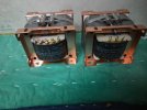
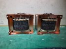
I would probably not go ahead with replacing the top wooden plate with a brass plate as that would require too many changes and efforts which i am not keen on doing now. Having decided on that, i went ahead and installed the new Poshan OPT on one channel yesterday as attached. All important voltages were accurate and i will have a plate dissipation of around 13.85 watts (this is around 35% of the KT88 max plate dissipation of 40 watts). The 6FQ7 driver tube is having a dissipation of 1.0435 watts (this is around 26% of the max plate dissipation for the 6FQ7 of 4 watts). The Poshan transformer can handle upto 20 watts of dissipation. I played for over two hours today morning and compared it with the other channel "Delta" transformer which would have clocked over 400+ hours in the past 3+ months and immediate observation was the Poshan had more top-end and was more airy. The "Delta" though had better low end imo. I am expecting the Poshan to improve on the low end after around 100+ hrs as now they are just out of the box.


Last edited:
I could complete the other monoblock yesterday and listen with both monoblocks connected yesterday evening for a couple of hours. My first few minutes/ hours of listening impression as below,
- POSHAN has more top end compared to my previous transformer.
- POSHAN sounds more focused, detailed and accurate.
- Delta transformer had more low end in comparison to POSHAN. I am expecting POSHAN to improve on this after 100+ hrs of playing.
- POSHAN is dead quite. I can't hear any hum whatsoever even if I place my ears on the woofer cone.
- Measured residual AC voltage at speaker terminal is just 2.5 mV.
- Mid-range is very open, liquid and like one to die for. The vocals sound as if they are in the room singing specially for me. String instruments and Piano sounds scary real. I could hear many new sounds playing in some music which were earlier masked. I could hear some studio background noise too in some recordings. This will give you an indication how juicy/detailed this Transformer is. But I actually did not want studio noise in my music but again I am not complaining. I can't imagine what to expect after 100+ hrs.
- Distortion is non-existient / or very low (if any). Zero fatigue even after listening for 2+ hrs without break.
FMs who have read my other post know that i am a big fan of silver plated copper wire and have used them as my signal wires. Now that is history. I have graduated to using a gold plated solid silver wire as my input wire. ie. input to ground and hot to driver grid. This being a naked solid silver gold plated, i used a pvc transparent tubing to house them with air dielectric. Thanks to FM @yogibear for giving this wire to me. The composition of this wire is 92.5% silver, 6% copper and 1.5% gold. I am expecting some more wire for my pre-amplifier.
Some images of my second monoblock -
Hari,
Are those two yellow wires, in the rear of the Output XFR...... leading to the rear of the amplifier, the XFR's secondary??
If so, there are two errors.
( You must have been so excited to get those double C - Core Poshans, that you did not fully think-out your best methodology..... for installation. We are all alike !! )
(1) You never ever twist the different polarities of the speaker leads, or have them even touch each other, as I can see you have done in the third photo up. I see you have them in a clear plastic tube, and twisted. Cut away that tube !!! Throw it away. Untwist and separate the wires.
I would also treat the primary leads the same way.
Drill a second hole in the chassis, for the primary leads and space the wires slightly apart, coming up through the chassis.
Also, error (2) is that you should use not a single 12 AWG run of m22759/11, ( to the speaker posts, from the secondary ) , but rather, use a 12 plus a 14 AWG paralleled run, ( for each positive and negative speaker lead polarity ) just exactly as you saw on that Softone RW-20 rewire - posted a couple days ago.
Transfer efficiency of the amp to speakers with 12+14 m22759/11 VS : a single 12 AWG run, will improve, as will a chance for the bass to play its best.
- - - - - - - - - - - - - - - - - - - - - - - - - - - - - - - - - - - - -
Do you recall, maybe a couple of months ago, what sonic benefit resulted when I asked you to cut off all the tie wraps you had used, ( to neatly visually bundle the wires below-deck ), and I had you separate the wires - so they their fields did not interact ???
Recall that sonic effect / improvement ?
This same concept fully applies every inch along the way, from the input of the amplifier, ( and the interconnects that feed the amplifier ) to the voice coils of your speakers.
- - - - - - - - - - - - - - - - - - - - - - - - - - - - - - - - - - - - - - - - - -
Re-do it correctly . Execute your own DIY build as good as you know how to do. All of this already has proven itself........to be audible and better sounding .
Have fun. Hook a CD player, on " repeat" to the input of the amp, put loading power resistors on the output, and let it play for several days, or better yet, weeks, in complete silence. That will get you a break in of the new iron. It can take 100 to 400 hours. Bottom end will eventually develop.
Off topic : Whats the VDC on the plate of the 6FQ7 Input/Driver tube, recall the measurement ??
Thank you.
Last edited:
Hari,
Are those two yellow wires, in the rear of the Output XFR...... leading to the rear of the amplifier, the XFR's secondary??
If so, there are two errors.
( You must have been so excited to get those double C - Core Poshans, that you did not fully think-out your best methodology..... for installation. We are all alike !! )
(1) You never ever twist the different polarities of the speaker leads, or have them even touch each other, as I can see you have done in the third photo up. I see you have them in a clear plastic tube, and twisted. Cut away that tube !!! Throw it away. Untwist and separate the wires.
I would also treat the primary leads the same way.
Drill a second hole in the chassis, for the primary leads and space the wires slightly apart, coming up through the chassis.
Also, error (2) is that you should use not a single 12 AWG run of m22759/11, ( to the speaker posts, from the secondary ) , but rather, use a 12 plus a 14 AWG paralleled run, ( for each positive and negative speaker lead polarity ) just exactly as you saw on that Softone RW-20 rewire - posted a couple days ago.
Transfer efficiency of the amp to speakers with 12+14 m22759/11 VS : a single 12 AWG run, will improve, as will a chance for the bass to play its best.
- - - - - - - - - - - - - - - - - - - - - - - - - - - - - - - - - - - - -
Do you recall, maybe a couple of months ago, what sonic benefit resulted when I asked you to cut off all the tie wraps you had used, ( to neatly visually bundle the wires below-deck ), and I had you separate the wires - so they their fields did not interact ???
Recall that sonic effect / improvement ?
This same concept fully applies every inch along the way, from the input of the amplifier, ( and the interconnects that feed the amplifier ) to the voice coils of your speakers.
- - - - - - - - - - - - - - - - - - - - - - - - - - - - - - - - - - - - - - - - - -
Re-do it correctly . Execute your own DIY build as good as you know how to do. All of this already has proven itself........to be audible and better sounding .
Have fun. Hook a CD player, on " repeat" to the input of the amp, put loading power resistors on the output, and let it play for several days, or better yet, weeks, in complete silence. That will get you a break in of the new iron. It can take 100 to 400 hours. Bottom end will eventually develop.
Off topic : Whats the VDC on the plate of the 6FQ7 Input/Driver tube, recall the measurement ??
Thank you.
Thanks Jeff for the advise. Will execute this as per your suggestion this weekend.Hari,
Are those two yellow wires, in the rear of the Output XFR...... leading to the rear of the amplifier, the XFR's secondary??
If so, there are two errors.
( You must have been so excited to get those double C - Core Poshans, that you did not fully think-out your best methodology..... for installation. We are all alike !! )
(1) You never ever twist the different polarities of the speaker leads, or have them even touch each other, as I can see you have done in the third photo up. I see you have them in a clear plastic tube, and twisted. Cut away that tube !!! Throw it away. Untwist and separate the wires.
I would also treat the primary leads the same way.
Drill a second hole in the chassis, for the primary leads and space the wires slightly apart, coming up through the chassis.
Also, error (2) is that you should use not a single 12 AWG run of m22759/11, ( to the speaker posts, from the secondary ) , but rather, use a 12 plus a 14 AWG paralleled run, ( for each positive and negative speaker lead polarity ) just exactly as you saw on that Softone RW-20 rewire - posted a couple days ago.
Transfer efficiency of the amp to speakers with 12+14 m22759/11 VS : a single 12 AWG run, will improve, as will a chance for the bass to play its best.
- - - - - - - - - - - - - - - - - - - - - - - - - - - - - - - - - - - - -
Do you recall, maybe a couple of months ago, what sonic benefit resulted when I asked you to cut off all the tie wraps you had used, ( to neatly visually bundle the wires below-deck ), and I had you separate the wires - so they their fields did not interact ???
Recall that sonic effect / improvement ?
This same concept fully applies every inch along the way, from the input of the amplifier, ( and the interconnects that feed the amplifier ) to the voice coils of your speakers.
- - - - - - - - - - - - - - - - - - - - - - - - - - - - - - - - - - - - - - - - - -
Re-do it correctly . Execute your own DIY build as good as you know how to do. All of this already has proven itself........to be audible and better sounding .
Have fun. Hook a CD player, on " repeat" to the input of the amp, put loading power resistors on the output, and let it play for several days, or better yet, weeks, in complete silence. That will get you a break in of the new iron. It can take 100 to 400 hours. Bottom end will eventually develop.
Off topic : Whats the VDC on the plate of the 6FQ7 Input/Driver tube, recall the measurement ??
Thank you.
The 6FQ7 vdc (Direct couple point) is 202 VDC with mains as 247 VAC.
Wharfedale Linton Heritage Speakers in Red Mahogany finish at a Special Offer Price. BUY now before the price increase.
Similar threads
- Replies
- 27
- Views
- 1K