You are using an out of date browser. It may not display this or other websites correctly.
You should upgrade or use an alternative browser.
You should upgrade or use an alternative browser.
Help required for designing a crossover for my speakers
- Thread starter Bordoloi
- Start date
How did you measured the driver response? Can you share photos of the measurement setup you had. Designing a crossover needs a lot of experience, its not an easy task. Proper tools & environment is needed to have good measurement of drivers. You will need to take many measurements like Far field, Near field, Port response, then calculate Baffle step compensation, etc etc. After that you can generate frd & zma files which are necessary to design Crossovers, I would advice you to find and read more about taking measurements of drivers, understand the process. This will be your first step towards designing a cross over.
Cross overs, there are basically two types electronic and passive, again it have sub filters like 1st order 2nd order 3rd order & 4th order, try to read and understand about them. Understand where and how these filters are used. Read about choosing the right crossover point for the selected drivers. there are many factors to understand and learn to design a crossover.
Looking at a crossover looks a simple job, But designing a cross over is not simple task, It takes many years of experience to get it right. In any speaker crossover is the important factor for its performance.
Vineethkumar01
Well-Known Member
If you haven't already seen these,
I would suggest you to go through courses on this website (available on sites like Udemy. It may cost around Rs 500 for each course which is a well worth investment in my opinion, if you want to build speaker that do at least basic things right ):
 audiojudgement.com
It has courses on different aspects of speaker building and in particular a course about crossover design. It is good for an absolute beginner. It will help one get a better idea of the whole process step by step.
However, please note that I am recommending the above course due to the lack(/my lack of knowledge) of better structured and more detailed 'courses' on these aspects. All these typical courses seem to be focused on getting a typical 'on-axis' sound right approach.
Personally, I will never again do crossover work based on just on-axis measurements. They will only tell a very small part of the picture unless one is an experienced designer. For anyone else serious about speaker building, I would suggest investing in a good set of measurement equipment such as an audio interface and non-usb MICs, studying how to use VituixCAD, and taking and studying full polar measurements of the drivers in the intended cabinet (0-90/180 degrees in at least 10 degree steps) and then approach designing a crossover.
This will give more predictable results about the general behavior of the speaker anechoically and in-room.
I would suggest you to go through courses on this website (available on sites like Udemy. It may cost around Rs 500 for each course which is a well worth investment in my opinion, if you want to build speaker that do at least basic things right ):
Courses
However, please note that I am recommending the above course due to the lack(/my lack of knowledge) of better structured and more detailed 'courses' on these aspects. All these typical courses seem to be focused on getting a typical 'on-axis' sound right approach.
Personally, I will never again do crossover work based on just on-axis measurements. They will only tell a very small part of the picture unless one is an experienced designer. For anyone else serious about speaker building, I would suggest investing in a good set of measurement equipment such as an audio interface and non-usb MICs, studying how to use VituixCAD, and taking and studying full polar measurements of the drivers in the intended cabinet (0-90/180 degrees in at least 10 degree steps) and then approach designing a crossover.
This will give more predictable results about the general behavior of the speaker anechoically and in-room.
Thanks for your reply Mr. Sadik. I took the measurements using UMIK1 and REW. Unfortunately I don't have any photo to share until next time I do the measurements again. I raised the speaker to 1.5 m from the floor as its about half the height of my room. I had generated the FRDs for far field at 1m on axis using 1watt and ZMAs using DATS V3.I can understand that designing the right crossover is a art and I am trying to learn that. I initially thought of going for miniDSP as active crossover but learning to design passive crossover will be a skill I should be good at.How did you measured the driver response? Can you share photos of the measurement setup you had. Designing a crossover needs a lot of experience, its not an easy task. Proper tools & environment is needed to have good measurement of drivers. You will need to take many measurements like Far field, Near field, Port response, then calculate Baffle step compensation, etc etc. After that you can generate frd & zma files which are necessary to design Crossovers, I would advice you to find and read more about taking measurements of drivers, understand the process. This will be your first step towards designing a cross over.
Cross overs, there are basically two types electronic and passive, again it have sub filters like 1st order 2nd order 3rd order & 4th order, try to read and understand about them. Understand where and how these filters are used. Read about choosing the right crossover point for the selected drivers. there are many factors to understand and learn to design a crossover.
Looking at a crossover looks a simple job, But designing a cross over is not simple task, It takes many years of experience to get it right. In any speaker crossover is the important factor for its performance.
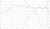
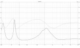
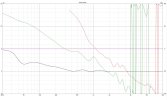
Thank you for the suggestions Mr Vineeth.I had gone through the courses you mentioned ,several times. In fact if you are a subscriber to Skillshare.com, you get all of his courses to study and I have personal communication with Tanasescu Marius(owner of audiojudgement).He is a very helpful guy.I have generated the design that I attached to the thread using VituixCAD.If you haven't already seen these,
I would suggest you to go through courses on this website (available on sites like Udemy. It may cost around Rs 500 for each course which is a well worth investment in my opinion, if you want to build speaker that do at least basic things right ):
It has courses on different aspects of speaker building and in particular a course about crossover design. It is good for an absolute beginner. It will help one get a better idea of the whole process step by step.Courses
audiojudgement.com
However, please note that I am recommending the above course due to the lack(/my lack of knowledge) of better structured and more detailed 'courses' on these aspects. All these typical courses seem to be focused on getting a typical 'on-axis' sound right approach.
Personally, I will never again do crossover work based on just on-axis measurements. They will only tell a very small part of the picture unless one is an experienced designer. For anyone else serious about speaker building, I would suggest investing in a good set of measurement equipment such as an audio interface and non-usb MICs, studying how to use VituixCAD, and taking and studying full polar measurements of the drivers in the intended cabinet (0-90/180 degrees in at least 10 degree steps) and then approach designing a crossover.
This will give more predictable results about the general behavior of the speaker anechoically and in-room.
Why do you suggest using non USB mics?I use UMIK1
Vineethkumar01
Well-Known Member
Ok. Since you have gone through the courses, I assume you have the basic knowledge about filter topologies implemented via passive elements in this case. This is good. The reason for suggesting non-USB mics is because with USB mics, it is hard to set up timing reference, which is needed for dual channel/semi dual channel measurements as recommended/required by VituixCAD for good crossover design.Thank you for the suggestions Mr Vineeth.I had gone through the courses you mentioned ,several times. In fact if you are a subscriber to Skillshare.com, you get all of his courses to study and I have personal communication with Tanasescu Marius(owner of audiojudgement).He is a very helpful guy.I have generated the design that I attached to the thread using VituixCAD.
Why do you suggest using non USB mics?I use UMIK1
From whatever I know, the simplest way this can be accomplished is by using an audio interface/soundcard and with a mic compatible with it. I personally use an ESI sound card with Dayton EMM-6 measurement mic, which is among the most affordable options available to a DIYer (not necessarily having the best accuracy w.r.t mic but still acceptable). The timing reference in such a system is obtained via internal/external loopback in the sound card.
People do indeed recommend crossover design using the minimum phase responses derived from the frequency response measurements obtained via single channel measurements using usb mics such as UMIK-1. Many People have used this to design good speakers in the past too. However, to do that one needs good experience/need to be lucky. The minimum phase response may hold good in characterizing the phase response in the linear region of the frequency response. However, its accuracy is debatable in regions where non-linearities take over, close to which are the regions which are usually the most affected by crossovers. Measurement of actual phase response is also needed for getting reliable off-axis frequency response data.
If you have used VituixCAD, also take a look at its manual. The author of VituixCAD, Kimmosto, explicitly recommends against using USB mics for crossover design. He also recommends getting full polar/angular measurements, horizontally and vertically. This is essential to characterize the speaker performance at least to a reasonably good extent.
Are these frequency response measurements taken after fitting the drivers in their final cabinet?
Last edited:
Ok I got your reason for recommending non USB mics.Hope I had known it before purchasing UMIK1.I will go through VituixCAD manual.Thanks for pointing it out,I never bothered to read it.And yes those measurements were taken using the final cabinetOk. Since you have gone through the courses, I assume you have the basic knowledge about filter topologies implemented via passive elements in this case. This is good. The reason for suggesting non-USB mics is because with USB mics, it is hard to set up timing reference, which is needed for dual channel/semi dual channel measurements as recommended/required by VituixCAD for good crossover design.
From whatever I know, the simplest way this can be accomplished is by using an audio interface/soundcard and with a mic compatible with it. I personally use an ESI sound card with Dayton EMM-6 measurement mic, which is among the most affordable options available to a DIYer (not necessarily having the best accuracy w.r.t mic but still acceptable). The timing reference in such a system is obtained via internal/external loopback in the sound card.
People do indeed recommend crossover design using the minimum phase responses derived from the frequency response measurements obtained via single channel measurements using usb mics such as UMIK-1. Many People have used this to design good speakers in the past too. However, to do that one needs good experience/need to be lucky. The minimum phase response may hold good in characterizing the phase response in the linear region of the frequency response. However, its accuracy is debatable in regions where non-linearities take over, close to which are the regions which are usually the most affected by crossovers. Measurement of actual phase response is also needed for getting reliable off-axis frequency response data.
If you have used VituixCAD, also take a look at its manual. The author of VituixCAD, Kimmosto, explicitly recommends against using USB mics for crossover design. He also recommends getting full polar/angular measurements, horizontally and vertically. This is essential to characterize the speaker performance at least to a reasonably good extent.
Are these frequency response measurements taken after fitting the drivers in their final cabinet?
Vineethkumar01
Well-Known Member
If you could share a picture of the cabinet, drivers used, the circuit topology being used in getting this frequency response shown above, I think other experienced members on this forum can also help you with tweaking the crossover circuit to get your desired response.Ok I got your reason for recommending non USB mics.Hope I had known it before purchasing UMIK1.I will go through VituixCAD manual.Thanks for pointing it out,I never bothered to read it.And yes those measurements were taken using the final cabinet
I personally have experience only using active/DSP filters to arrive at my desired frequency response curves. I personally will never tweak the circuit/filter responses to straighten out only the ON-axis curve at the expense of the smoothness of the the off-axis curves.
Sure I will take pictures and upload here.Another question is I read somewhere that one guy uses miniDSP to design his passive crossovers.How is that possible?If you could share a picture of the cabinet, drivers used, the circuit topology being used in getting this frequency response shown above, I think other experienced members on this forum can also help you with tweaking the crossover circuit to get your desired response.
I personally have experience only using active/DSP filters to arrive at my desired frequency response curves. I personally will never tweak the circuit/filter responses to straighten out only the ON-axis curve at the expense of the smoothness of the the off-axis curves.
Vineethkumar01
Well-Known Member
The only way I can think of using MiniDSP in aiding passive crossover design is in designing prototype crossovers for testing different crossover configurations. Essentially, it means building an active crossover-based system first, try different crossover filters in miniDSP. Once you find the configuration which suites your subjective/objective tastes, then implement the filters using an analog circuit (Resistor, capacitor, inductor components), which essentially forms the final passive crossover.Sure I will take pictures and upload here.Another question is I read somewhere that one guy uses miniDSP to design his passive crossovers.How is that possible?
The other way in which MiniDSP can be used with passive-crossovered speakers is in equalization. Either adjusting based on in-room response of the speakers or based on some other criteria.
mallikreddyk
Member
Dont put too much emphasis on flat response. Please understand that a reasonable variance of +/-1.5 to +/-3db is an acceptable response. And since troughs are desirable than peaks, the target should be between +1.5 to -3db from the mean.
Now that we have the basics out of the way. the next step is to provide adequate information for the members to help you.
1. Pics
2. Driver model numbers
3. FRD and Zma files.
4. post the full schematic not just the output, else nobody knows what you are doing. we need to be able to first replicate the issue to resolve it.
Thanks
Mallik
Join WhatsApp Channel to get HiFiMART.com Offers & Deals delivered to your smartphone!
Similar threads
- Replies
- 6
- Views
- 5K


