businessbysaud
New Member
Also. Could the buzzing sound i heard be the mobile charger shorting?

1. The receiver will not turn on if the power supply has gone totally deadThis will cause the reciever to not turn on?
Like main on button does nothing. If i press tone+info+power. The reciever blinks red light twice. And then stays off.
Is this MOD culprit or something else is bugging?

Yes. It looks like the mobile charger has gone bad. But only way to find that out is to use a multimeter and check the output on the two wiresAlso. Could the buzzing sound i heard be the mobile charger shorting?
Yes. It looks like the mobile charger has gone bad. But only way to find that out is to use a multimeter and check the output on the two wires. But be careful. YOu have live voltage on that board.
If speaker shows 0 ohm that means its short.If its so,then Avr will shut down on volume increase.I just figured something with multimeter. my aiwa center and front L/R speakers read 0ohms on the speaker binding post terminals. will they be shorting the amp? OH FFF
my remaining kenwood surround L/R and Surround back L/R read good resistance with multimeter.
I'm asking a stupid question. I hope you didn't measure the resistance with the speakers connected to the AVR. You can connect the kernwood surround L/R to L/R and play it at low volume to see.I just figured something with multimeter. my aiwa center and front L/R speakers read 0ohms on the speaker binding post terminals. will they be shorting the amp? OH FFF
my remaining kenwood surround L/R and Surround back L/R read good resistance with multimeter.
if i am not wrong any 8ohm speaker should read beteween 5-7 ohm on dc resistance.
I thought that too. But its not the case. Some cross overs have inductors(i think those are called inductors not sure) which shows no resistance/open circuit.If speaker shows 0 ohm that means its short.If its so,then Avr will shut down on volume increase.
It didn't show any. I MEAN "ANY" kind of error.I'm asking a stupid question. I hope you didn't measure the resistance with the speakers connected to the AVR. You can connect the kernwood surround L/R to L/R and play it at low volume to see.
In general when the speaker terminals get shorted, the AVR displays "Speaker PRT"
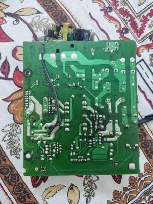
Yes through a connector.I want to know one thing. Video2 board is attached to a board below it.
Correct.I removed 3 screws(two on sides, one in back) to get access to the mobile charger(the mod) but i think video2 is linked through a port/some linkage with the board below.
You just have to pull it up with a slight force. The board will come out of the connector on the board below. While fitting it back, you have to align the board male connector over the female connector and push it with a slight force.I didn't want to force it so i left it as it is. Can i know how do i remove video2 board?
This is the video2 board. What do you think of it?Yes through a connector.
Correct.
You just have to pull it up with a slight force. The board will come out of the connector on the board below. While fitting it back, you have to align the board male connector over the female connector and push it with a slight force.
The person who repaired it earlier has done a heart bypass for the boardThis is the video2 board. What do you think of it?
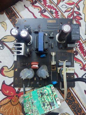
It's outputting this range: 5.12v - 5.15vThe person who repaired it earlier has done a heart bypass for the board
That extra board has two white wires taking the mains power.
The two black wires have the 5.5 volts supply.
You can test it this way
Remove the power cord from the yamaha avr.
Insert that end of the power cord into this board. First put this board properly on a wooden board. Connect a multimeter leads to the two black wires.
Switch on the power supply and see what the multimeter shows. Be careful. Don't touch the board with bare hands with the power supply on.
EDIT: I can already see that you haven't disconnected the power cord. So you just have to connect the power supply and measure the voltage.
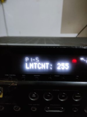
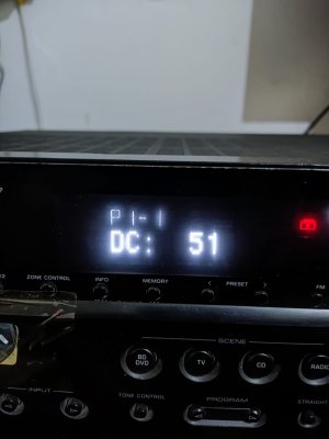
I think it is low. 5.5v is not exactly required but this power is required for the HDMI board which also has the microprocessor and does protection of the AVR. To confirm if it is being sensed as low, you will have to open the service manual and turn on the system diagnostics and get the PS1/PS2 value. This is from page 24 of service manual. You will have to read the service manual and learn how to turn on diagnostics. It is not difficult. Just read the manualIt's outputting this range: 5.12v - 5.15v
Should it be exactly 5.5 for the power to work?


I took these pictures a week ago when the avr turned on for a short time.I think it is low. 5.5v is not exactly required but this power is required for the HDMI board which also has the microprocessor and does protection of the AVR. To confirm if it is being sensed as low, you will have to open the service manual and turn on the system diagnostics and get the PS1/PS2 value. This is from page 24 of service manual. You will have to read the service manual and learn how to turn on diagnostics. It is not difficult. Just read the manual
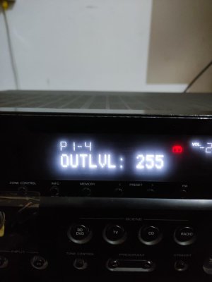
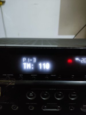
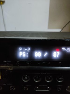
PS1 should be in the range 38-141
PS2 should be in the range 34-138
View attachment 71761
View attachment 71762
View attachment 71763
These are all normal. The problem is the AVR shuts off only when the voltage becomes abnormal and that's the voltage you need. This is what was happening with my AVR too.I took these pictures a week ago when the avr turned on for a short time.
if the avr starts up i can check. but if you can give me guide what to look for i might be able to get you the informationThese are all normal. The problem is the AVR shuts off only when the voltage becomes abnormal and that's the voltage you need. This is what was happening with my AVR too.
There is a way to look at the Protection History. Can you see if there is anything in the protection history?
You can do an easier thing. Refer to this photo of yours. There are two black wires coming from that extra SMPS board that the earlier repairer has fitted.if the avr starts up i can check. but if you can give me guide what to look for i might be able to get you the information