let me try to recollect the sequence of events what happened to me when i built mine (please excuse the lack of memory, it is from many decades ago)
- On first power up, i recollect it was dead, i recollect Dad coming and having a laugh, where's the ferrite rod? (i had wound my own aerial coil) without a ferrite rod I think on some paper rolled over a pen cap or something. The next day on his way back from office, a small 4 inch ferrite rod with 2 plastic holders duly arrived
- Slipped the aerial coil over the ferrite rod, no sound, dead. Checked the aerial coil with my 6 volt bulb tester, for some reason it was open, so Dad got me a ready-made one the next day with those fiberous thin wires and I wired that in, replacing the copper wire coil. Still dead.
- The original circuit by Sandeep Baagchi was built around AC125, i had used a spare 2N369 transistor which dad got me for making a morse code practice oscillator. Dad dug into his parts bag and gave me a AC125 and AC126 transistor pair, I replaced the 2N369 with an AC126 transistor (if i recollect correctly my wishful thinking was 126 is greater than 125 so I'll get more power from the transmitter). However, I dont remember exactly what happened, whether I overheated it while soldering or the leg broke, but anyways AC126 was damaged and I had to revert back to AC125 after an old school lecture from Dad on how to use a tweezer between the end of the leg being soldered and the transistor to protect the transistor from burning out. Great progress I was able to tune to a whoosh sound on the radio but i hadnt connected any input so did not hear anything
- Dad then gave me a feed from one channel of his turntable, with EEI CS2000 ceramic cartridge. My initial build did not have the input coupling 10mfd cap, selector switch or volume Pot. The original design by Sandeep had the Pickup cartridge connected directly into the base of the transistor and I had this same approach. Finally, I could hear music playing on the radio but the volume was very low and distorted, Dad advised to change the 2.2k to 10k and boom, it became loud and clear
- We then tried the output of his tape deck. Very high distortion and clipping. So he came up with the idea of the input cap (10mfd) and the volume Pot after which, i could adjust the volume and the distortion disappeared.
Note: I noticed that you have used a RF transistor, please use a AF transistor, I have tried RF transistors in later experiments with this circuit and they never worked. Many days after the AC125 success I tried BC149C with reversed battery polarity and it worked as well, but I felt AC125 sounded more soft and clean, whereas the BC149 sounded like it was overdriving the circuit
Important: Use a piece of wire as an aerial but ensure that the wire is not grounded or you dont touch it. I recollect that if I touched the collector of the transistor, the aerial coil, the gang capacitor active pins the 0.005uf capacitor or the aerial, transmission would stop and would resume after I removed my fingers from the vicinity.
Useful: As i was a little kid, dad would not let me play with electricity, so i had an old school battery box which held upto 6 x 1.5 volts torch batteries (9 volts), by slipping the connecting jumper plate one step forward, one could use 4 x 1.5 volts batteries and get 6 volts. This was my power source. Years later i had tried this circuit with my battery eliminator (I had a switchable one with 9v and 6v) and it did not work well due to some electric hum and inteference. Batteries always gave the best results.
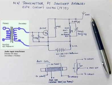
Here is the original schematic without the input additions and with the 10k mod. I later added those input extras in order to drive the transmitter with the line output of a cassette deck.
View attachment 72605
I know all this may sound very ancient and dumb in the modern context but for little ordinary kids like us in those gloroius old days without google or even reference books, these little gadgets were stunning achievements and allowed us to earn the tag of "brilliant child", "future scientist" etc in our times. Thanks for helping me to re-live those great memories!
Also I found this other circuit online which is similar to the one from Sandeep Baagchi, which I constructed. This one has a condenser microphone preamp and also uses BC109C transistors instead. Probably the 1k and condenser microphone can be elimanated and a normal line input feed, can be used instead.
View attachment 72607

robu.in

")


 . I used to read it in Manorama Book Stall near my house and drool over getting it.