You are using an out of date browser. It may not display this or other websites correctly.
You should upgrade or use an alternative browser.
You should upgrade or use an alternative browser.
My Own Harbeth’s + JBL's.... 3 Way Passive Speakers
- Thread starter sadik
- Start date


The stands are at my home. And these speakers are at my works. Those tables are temporary arrangement.
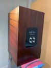
You are Pioneer of in the field of DIY. Best Quality of the materials! Superb perfection! God Bless You.After a very long time finally my speakers are moving towards finishing stage. Below are photo of clear coat done on enclosures. I have applied masking tape & they are now getting ready for next stage.
View attachment 64672
View attachment 64675
View attachment 64673
View attachment 64674
Sadik
RajithKumar
Well-Known Member
Very Nice Appreciate the great DIY efforts to create these beauties.
Please post the listening impressions , measurements etc.
Please post the listening impressions , measurements etc.
Here is the STEP response. You can shed some light on this graph cz i am not so familiar with reading this response.As discussed will it be possible to post a image of the step response?

Vineethkumar01
Well-Known Member
Here is my attempt to extract some information from the step response plot. Technically, the step response is the integral of the impulse response of a device under test (DUT), here it being a 3 way speaker with driver responses shaped by the crossover circuit.Here is the STEP response. You can shed some light on this graph cz i am not so familiar with reading this response.View attachment 65757
For a loudspeaker, the step response tells about the "time coherence" of the the different drivers tied together by the crossover. In a typical 3 way speaker with the tweeter, midrange and the woofer placed on a flat baffle, for a typical measurement axis (around the tweeter center or somewhere around it), at the mic position, the tweeter response arrives first, followed by the midrange response, followed by the woofer response.
In the above picture, the initial peak around zero seems to be the tweeter response, then the negative peak around 200us appears to be that of the midrange and the positive peak around 1ms appears to be that of the woofer.
The fact that all three peaks look clearly separated tells that the speaker is not time-coherent/drivers are not "time-aligned". In fact an estimate of the distance between the acoustic centers of the tweeter, midrange, and woofer can be made by computing the delay between the peak locations and converting it into distance (in mm or cm).
Ideally we want the step response to be like a right triangle, the initial sharp rise followed by a gradual decay (and peaks not going up and down). As the step down from that ideal, we would like to see smooth transitions all around in the response, without any abrupt peaks and dips.
Since time delay between drivers also indicate about the phase difference, this response also speaks about the relative phase differences between drivers. For example, we can see that in this case, the tweeter and woofer appears to be in phase, whereas the midrange is 180 degree out of phase with the tweeter and woofer.
Time-coherent devices are good from a theoretical perspective, but how much of that translates into listening experience is a controversial subject..
") Frequency response plots both on and off axis (hence the directivity) in combination with other things seems to have more correlation with perceptual sound quality (allthough the impulse response, step response and frequency response are all tightly connected by math).
Frequency response plots both on and off axis (hence the directivity) in combination with other things seems to have more correlation with perceptual sound quality (allthough the impulse response, step response and frequency response are all tightly connected by math).More info could be gleaned from the step response by more knowledgeable/experienced people. So we can wait for others to comment more about more step response related aspects.
Thanks
Vineeth
Vineethkumar01
Well-Known Member
Just to add more information:Here is my attempt to extract some information from the step response plot. Technically, the step response is the integral of the impulse response of a device under test (DUT), here it being a 3 way speaker with driver responses shaped by the crossover circuit.
For a loudspeaker, the step response tells about the "time coherence" of the the different drivers tied together by the crossover. In a typical 3 way speaker with the tweeter, midrange and the woofer placed on a flat baffle, for a typical measurement axis (around the tweeter center or somewhere around it), at the mic position, the tweeter response arrives first, followed by the midrange response, followed by the woofer response.
In the above picture, the initial peak around zero seems to be the tweeter response, then the negative peak around 200us appears to be that of the midrange and the positive peak around 1ms appears to be that of the woofer.
The fact that all three peaks look clearly separated tells that the speaker is not time-coherent/drivers are not "time-aligned". In fact an estimate of the distance between the acoustic centers of the tweeter, midrange, and woofer can be made by computing the delay between the peak locations and converting it into distance (in mm or cm).
Ideally we want the step response to be like a right triangle, the initial sharp rise followed by a gradual decay (and peaks not going up and down). As the step down from that ideal, we would like to see smooth transitions all around in the response, without any abrupt peaks and dips.
Since time delay between drivers also indicate about the phase difference, this response also speaks about the relative phase differences between drivers. For example, we can see that in this case, the tweeter and woofer appears to be in phase, whereas the midrange is 180 degree out of phase with the tweeter and woofer.
Time-coherent devices are good from a theoretical perspective, but how much of that translates into listening experience is a controversial subject..
More info could be gleaned from the step response by more knowledgeable/experienced people. So we can wait for others to comment more about more step response related aspects.
Thanks
Vineeth
Section F here in linkwitzlab website elaborates on step response and its connection with other aspects:
The tweeter arrives before the midrange shown by the first +ve spike, the midrange takes over at the top of this pulse and is reverse connected. The woofer takes over the midrange with a small disconnect which is shown by the small wrinkle in the waveform. The woofer is connected with +ve polarity. Btw, phase incoherent doesn't mean bad sounding. Only 4 to 5 speakers brand in the world can measure a perfect step response ( as known to me) and that require proper driver offset and proper driver spacing depending upon crossover frequency. It require proper planning for the boxes and crossover design. Series crossover topology can help IME.Here is the STEP response. You can shed some light on this graph cz i am not so familiar with reading this response.View attachment 65757
Sadik,
What lovely eye candy !!! Very very nice. Hats -off to you.
If it sounds good to you, makes you happy to hear it, after listening for six months, that is ALL that matters !!
Thanks for sharing with us all.
Jeff
What lovely eye candy !!! Very very nice. Hats -off to you.
If it sounds good to you, makes you happy to hear it, after listening for six months, that is ALL that matters !!
Thanks for sharing with us all.
Jeff
Sadik,
None of us observant F.M.s could get ANY sleep last night !
In the beautiful crossover picture, the arrows on the " IN " High Definition speaker wire are pointing the wrong way.
Hopefully, we will all sleep better tomorrow, just from our own personal sheer exhaustion.
")
Jeff
None of us observant F.M.s could get ANY sleep last night !
In the beautiful crossover picture, the arrows on the " IN " High Definition speaker wire are pointing the wrong way.
Hopefully, we will all sleep better tomorrow, just from our own personal sheer exhaustion.
Jeff
Last edited:
I too just noticed it... lolSadik,
None of us observant F.M.s could get ANY sleep last night !
In the beautiful crossover picture, the arrows on the " IN " High Definition speaker wire are pointing the wrong way.
Hopefully, we will all sleep better tomorrow, just from our own personal sheer exhaustion.
Jeff
I too just noticed it... lol
One other little thing or two about wire to suggest / simply mention, for you to think about....... and someday experiment with.
The late Pierre Sprey of Mapleshade Audio, told us we should have speaker polarities " to the speaker from the amp, and internally inside the speaker, from crossover to drivers, totally separated from each other". It sounds better that way. ( Why, less capacitance ).
On ALTEC VOTT A7-8s I find this absolutely so, noticeable as more air, in " the highs ". Pierre is correct, on my high efficiency set up. It likely applies to some degree ( totally unknown to me ) on lower efficiency speakers.
Just two days ago, I bought vintage glass telephone pole wire insulators from a local antique store, to keep polarities 100% separated nicely, amplifier to speaker crossover.
Find out, on HFV about wire Polarities, and Mapleshade wiring tips, in this specific post :
New Design, SE 6005 Directly Coupled Audio Amplifier
1-1-2022 ................................ Wire Management of your own AUDIO SYSTEM...................................................... Several times in the last 14 months I have been on H.F.V., I have enthusiastically referred F.M.s to Mapleshade Audio's web page entitled " Wire Management...
There exists one other thing to experiment with Sadik.
India has a large population. Internal room space in India on average is smaller than less densely populated countries. There is usually NOT much distance, between the electronics, and two stereo speakers, when the electronics are centrally located.
Notice please, Pierre's important findings, that a four foot speaker cable distance, is always worse sounding than an eight foot cable length run. ( LOL, but also realize, you can not lay a longer speaker cable on the typical rug or floor surface, or have it touch anything plastic !! )
It is absolutely best, to suspend speaker cables totally in mid-air, and totally polarity separated when using high efficiency speakers !!!
In 2019, my audio mentor independently A-Bed these things on his home's large ALTEC ( 11 cubic feet ) high efficiency speakers, with superb electronics, and found Pierre's advice to be correct !!
Only ONE suggested ( and easy ) change I do have to Pierre's methods. Use two times 57 1/8th inches, or 114 1/4 inches, / 9.52 feet, as the basic speaker lead ( or an AC cord !! ) length. In each case, on high efficiency speakers, it was found to sound the best, VS shorter runs, of half that very specific distance !!
Well, this could keep you engaged for the next two to five years !!! Have fun listening Sadik.
Read Mapleshade's wire management page also, please copy it before it is taken down due to Pierre's death. He was bright in audio and life , a listener, and ON the money !!
Mighty cool to interact with you, brother Sadik.
Jeff
Last edited:
Somehow missed the final updates. Looks absolutely gorgeous! How do they look now on their own stands!?A fest for your eyes.
Congratulations!
These Beauties have already made their new home with kind gentleman from Bhatinda. However the stands are still with me.Somehow missed the final updates. Looks absolutely gorgeous! How do they look now on their own stands!?
Congratulations!
Wharfedale Linton Heritage Speakers in Walnut finish at a Special Offer Price. BUY now before the price increase.
Similar threads
- Replies
- 24
- Views
- 10K