Restoration Of Radio BX665X

Pandu Rajan

Member
Joined
Jul 19, 2013
Messages
62
Points
18
Location
Bangalore
Dear Friends

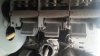
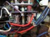
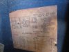
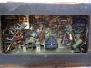
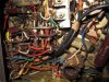
I am posting photos of the radio set Philips Holland make BX665X manufactured in 1947. I had earlier restored this set in 2002. At that time I did not have the necessary experience to restore vintage radio set correctly and properly. So I had painted the chasis with grey paint. Also I did not dismantle the set completely. This gave a very bad appearance and I was not at all satisfied with the job done. So I decided to do the restoration work again in a proper way by painting the chasis with Aluminium paint after complete dismantling the chasis which is in three parts. The rust was removed thoroughly and cleaning was done before painting. The result can be seen in the photos. The photos with grey paint are before re-restoration work was started.

w6j8.jpg

1lxq.jpg

rapr.jpg

nk08.jpg

oknp.jpg

pwtp.jpg

xncp.jpg

hg4q.jpg

ihv1.jpg

xyji.jpg

x8ho.jpg

imyc.jpg

wh57.jpg

d39p.jpg

u18t.jpg

gcwz.jpg


Regards

P.Rajan
 
You can see that it is a special 6-section gang. Three for the band spread bands and three for the regular bands. This gang was used by Philips Holland in some of their sets. I did not take the risk of painting the fins as by mistake if the paint got inside the fins it would lead to short circuiting of the fins and also jamming the movement of the fins. The gap between the fixed plates and the moving plates is bare minimum.

Regards

P.Rajan
You are absolutely correct. No need to fiddle around those fins as well as little trimmers. Improper handling, unnecessary painting and cleaning may mis-align it and/or stop its functioning. Paint/fast glue and corrosion removal liquids needs 3 times thought before using. Remember you may not able to align it properly to original glory if you don't have proper equipments and tools.
 
Before 1957 Philips manufactured all the high priced sets with tuned RF stage and therefore the gang condenser used to have three sections. After 1957 with the improvement in the technology and availability of better materials for the coils and the IFTs this was stopped. BX665X had 6 sections because of the band spread bands. Out of the 6 section, three sections which were used for band spreading had special vanes where the change in capacitance with respect to angle of rotation was less. The value was 110PF. The other three sections were the normal type having a value 500PF. In the 1st band the band spread was on 16m&20M, 2nd band -25m & 30m and the 3rd band 40m & 50m.
Philips India manufactured two sets B6CA37A/38A and B6CA57A/58A in the year 1964/66 which had the feature of the band spread. They were 6 band radios with three spread bands - 19m, 25m and 31m and SW1,SW2and MW normal bands. This was achieved by two gang condensers coupled together by Thread mechanism. One of the condenser was of the normal type with a value 500pf and the other was the special type having a value 110pf.
I am posting a photo of the set B6CA38A where this arrangement gas been used.
kz26.jpg


Regards

P.Rajan
 
Thanks so much, you revived some good old memories from my child hood. I recall Dad telling us that many shops back in the day, would not accept band-spread radios as they were difficult to align.

This is the radio we had (the AC/DC version of this radio) at home. Its long gone but I managed to find a page online which talks about a restoration project of the AC version.

Ferguson 454 and 104 mains valve radio wireless

This radio had a UL33 beam power output valve and its audio stage worked as my Dad's power-amp from the 1960s right up to 1972.
 
Hi Pandu Rajan,

I have a old tube radio set. It is Assembled in India (1960) by National Ekco which used to manufacture its tube radio sets in Fort area, Mumbai.
It has 8 bands. AM and SW and Pickup only.
I picked that one in year 2000 from near Bhendi Bazaar Mumbai.

Through a trained tube radio mechanic in Nasik,
1) First thing I tried with was to add FM circuit in Pickup band. It did not work well.

2) Second thing I noticed was that AM was very weak and noisy. The National Ekco set does not have a ferrite rod antenna inside the set. The mechanic removed EZ80 and replaced it with EZ 81 or 89, I dont remember numbver. This increased gain but also increased noise. :)

3) The third thing the mechanic tried was to add a ferrite rod antenna. He was not successful. My thought process was that if we add a ferrite rod antenna inside the AM tuning circuit the MW would get better.

Is it possible to add a ferrite rod antenna in the tube radio set, if the original design did not have one?
How to identify the terminals where to add the ferrite rod?

Please help.
 
my thoughts

1) First thing I tried with was to add FM circuit in Pickup band. It did not work well.
Very vintage radios were not designed for FM so by trying to add an FM band, you'd end up getting poor or no result with the risk of damaging the set or spoiling its originality.

2) Second thing I noticed was that AM was very weak and noisy. The National Ekco set does not have a ferrite rod antenna inside the set. The mechanic removed EZ80 and replaced it with EZ 81 or 89, I dont remember numbver. This increased gain but also increased noise. :)
EZ80 is the rectifier valve. not sure how replacing it can improve performance. However there is a possibility that the original rectifier valve may have been on its last legs. What is probably needed is for you to look at the condition of the RF valves and the alignment of the IFTs and trimmers.

3) The third thing the mechanic tried was to add a ferrite rod antenna. He was not successful. My thought process was that if we add a ferrite rod antenna inside the AM tuning circuit the MW would get better.
Again, if the circuit has not been designed for a ferrite rod based MW/LW antenna coil, there is no use trying to put one in. If the set is in good condition with good valves, you should get good results with a long wire aerial. Have you checked out the AM reception in your home, using another radio. It could be the quality of signal and interference at your place as well. Remember, when these radios were around in their hay-day, there were no mobile towers, CFL lights, motor-based electrical equipment, etc which caused interference.
 
Dear JSBhavsar

The first thing which I want to impress while restoring vintage radio sets is that we must not modify the circuit and it must be kept as original. Because we are not designers and we just have the expertise to restore the set by bringing to its original condition. The person who must have designed the set must have achieved the results after many days of painful work and then only it must have been brought in to the market. There must be some fault in the set and that is why it is not working properly. The fault must be found out and correct component values to be replaced. EZ80 and EZ81 are rectifier valves. The output current of EZ80 is 100ma and that of EZ81 is 200ma. for a single ended output valve EZ80 is more than sufficient and changing it to EZ81 will further load the filament winding of the main transformer without getting any gain. In the market FM tuners are available which can be kept outside without doing any changes inside the radio set and can be connected to the PU input. It will work fine. Connecting a ferrite antenna should not be done as the set has been designed to work with out the Ferrite antenna and if every thing is O.K. it must work.

Regards

P.Rajan
 
Thanks for the inputs received on my National Ekco. Thanks for the help. EZ80 to EZ81 was not done to improve performance. It was found that the EZ80 had turned very weak. The old mechanic did not have any EZ80 in his collection. I had spare EZ80s at home but he did not seek permission from me and he did not know whether I had tubes. Those were the days of 2000 when mobile phones were not much. When I visited him, he had made the change. EZ80 and EZ81 have different pins and so he had to do change. But he said other than the current increase, nothing much will change. Only change I noticed was the sound and volume had increased. He also changed the volume control switch as it had gone too weak from 1960 to 2000. He did not have the push-pull switch so he used similar type but the TURN ON kind of.
The set is really good especially 8 bands so one does get lot of space on SW bands, works really good on SW and MSW bands. However, it has completely lost on MW. The position of the tube radio is near to the large Sony TV containing picture and that is one reason why MW is so disturbed. New equipment like Broadband router and Set Top Box have got added in that proximity and so hopes of getting clear MW are gone.
I really really wanted to have a tube radio with a good strong tuned ferrite rod antenna especially for the MW. I saw some youtube videos with "ferrite sleeve antenna" and seen some differences. Western folks are using almost 40 or 60 ferrite rods tied together and then a coil on that huge sleeve. Very strong reception.

One another mystery recent times. We also have a Philips Trishul RL118 small tiny radio. It is able to receive All India Radio Najibabad at 954 khz at a distance of 1450 km in central india without any external aerial and that too at night 9:00pm. Sound is crystal clear as if broadcast is from my own city. This, I feel is the power of ferrite rod antenna in the radio set and a properly trimmed and tuned circuit. I have a new brand Panasonic RF-800U radio and it fails to receive or even pickup the same Najibabad station in the same window at same MW frequency at same time. Philips did make and does make some really good sets. Yet not each from Philips Europe is/was seen in India.

Thank you!
 
Dear Mr. Bhavsar

Do you have the service manual for the National ekco radio set A730/A731.
Both are 8 band sets.

Regards

P.rajan
 
Philips Trishul RL118 small tiny radio. It is able to receive All India Radio Najibabad at 954 khz at a distance of 1450 km in central india without any external aerial and that too at night 9:00pm. Sound is crystal clear as if broadcast is from my own city.

Philips transistor radios are very well designed and well calibrated. They are quite sensitive as well. The internal MW aerial coil, mounted on the Ferrite rod is usually well tuned and calibrated. By suitably changing the position of the radio, you can easily optimize MW reception. The gain of the RF stages is also quite high, being a solid state radio, when compared to a vintage valve radio. To match the performance of the transistor radio, you'll need to use a tuned long wire aerial, new RF valves and of course, the overall calibration of the aerial coils, oscillator coils and IF transformers has to be professionally done, not to forget the numerous trimmers that accompany the aerial and oscillator circuitry.
 
You are absolutely correct. No need to fiddle around those fins as well as little trimmers. Improper handling, unnecessary painting and cleaning may mis-align it and/or stop its functioning. Paint/fast glue and corrosion removal liquids needs 3 times thought before using. Remember you may not able to align it properly to original glory if you don't have proper equipments and tools.

True and agreed. Long back I was fiddling with my Dad's Philips India Model 15RB487 tube radio and I found dust on the its gang plates. I got a tooth brush and decided to clean the plates and inside( I thought dust free shining gang means better tuning and reception). In the process the outside plates broke and fell off as they were too thin.
I therefore left my National Ekco A731 8 band tube radio which has 3 section gang as they are though A731 has thicker aluminium plates.

Can dipping the gang in white petrol help clean the dust? How are the restoring team members here cleaning the gang in Europe/UK?
 

Attachments

  • EkcoA731_Gang.jpg
    EkcoA731_Gang.jpg
    20.1 KB · Views: 39
Dear Mr. Bhavsar

Do you have the service manual for the National ekco radio set A730/A731.
Both are 8 band sets.

Regards

P.rajan

No Sir, I do not have the A730 or A731 schematic circuit or service manual. I am still looking for the same in Mumbai as the company is long gone.

Below person Mr Yuvraj in Ajmer, India has some experience on National Ekco radios:
Antique Radio Repairs - Ajmer - TV - Video - Audio - vaishali nagar

I did speak to him in length.

Regards,

Jitendra Bhavsar
 
my thoughts

3) The third thing the mechanic tried was to add a ferrite rod antenna. He was not successful. My thought process was that if we add a ferrite rod antenna inside the AM tuning circuit the MW would get better.
Again, if the circuit has not been designed for a ferrite rod based MW/LW antenna coil, there is no use trying to put one in. If the set is in good condition with good valves, you should get good results with a long wire aerial. Have you checked out the AM reception in your home, using another radio. It could be the quality of signal and interference at your place as well. Remember, when these radios were around in their hay-day, there were no mobile towers, CFL lights, motor-based electrical equipment, etc which caused interference.

My home where the National Ekco A731 is placed is full of complexity. It sits 6 inches away from a CRT Sony TV. It sits below a Philips Fluorescent tube with electronic choke (no starter). The tube radio sits 16 inches away from a broadband internet router. It sits 16 inches away from a Digital Set Top Box (VHF for TV cable). With this kind, I dont expect justice to me from my National Ekco A731. A special and separate earthing may do some help but housing complexes may not allow that. Moreover, overnight the earthing rod and the copper plate underneath will be stolen.

Last week I put off each and every equipment in the house and kept only my radio ON. The sound output was crystal clear and no disturbance and noise, though MW remained unheard.

A Philips RL118 works quite well in the window frame on its internal rechargeable battery. Therefore the position of my tube radio is quite odd.
 
Attaching some internal pictures of National Ekco tube radio A731. The bobbin type coils have been given by the manufacturer instead of regular ferrite rod antenna inspite of 1959 and 1960 radios having ferrite rod aerials in the Ekco UK sets. Lack of ferrite rod antenna means poor peformance on my MSW and MW bands. Real reason why ferrite rod aerial was avoided for the export models A730 and A731 is not coming clear.
 

Attachments

  • IMG_2357.jpg
    IMG_2357.jpg
    19.5 KB · Views: 28
  • IMG_2364.jpg
    IMG_2364.jpg
    15.7 KB · Views: 27
  • IMG_2356.jpg
    IMG_2356.jpg
    21.9 KB · Views: 27
  • IMG_2359.jpg
    IMG_2359.jpg
    28.4 KB · Views: 28
Check out our special offers on Stereo Package & Bundles for all budget types.
Back
Top