Tracing The PeeCeeBee

shaan

Well-Known Member
Joined
Oct 5, 2012
Messages
268
Points
63
Location
Kolkata
Hello Friends!
First of all, Happy New Year!

Now,
You may or may not heard about VSSA, the Very Simple Symmetrical Amplifier popularized on the diyAudio forums by LazyCat. But a couple year ago I designed and printed a layout of one of the simplest versions of the amplifier that is called the "PeeCeeBee" and since then a couple of the boards are sitting in my main system without any change. And after 2 years, I feel like nothing has changed. It sounds good.

The original layout has been tried by many people and in general the amp has worked flawlessly without dominant pole compensation, which was surprising for those who use it, including me; a three stage amp has quite a lot of phase lag right? Well of course it does, but the device intrinsic capacitance and higher value feedback resistors were "just" keeping it from getting too excited about itself.

Many people has tried and tested this layout of this amplifier, with mostly encouraging results. However, all I could do was to guess, here and there. My system sounds real nice but I didn't know if there is anything funny going on in the upper band of it's frequency response, though the input has some RF filtering.

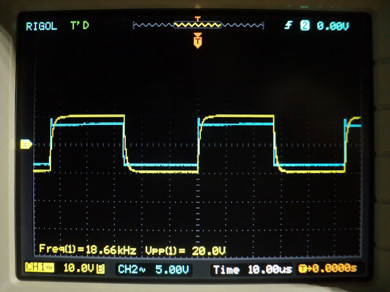
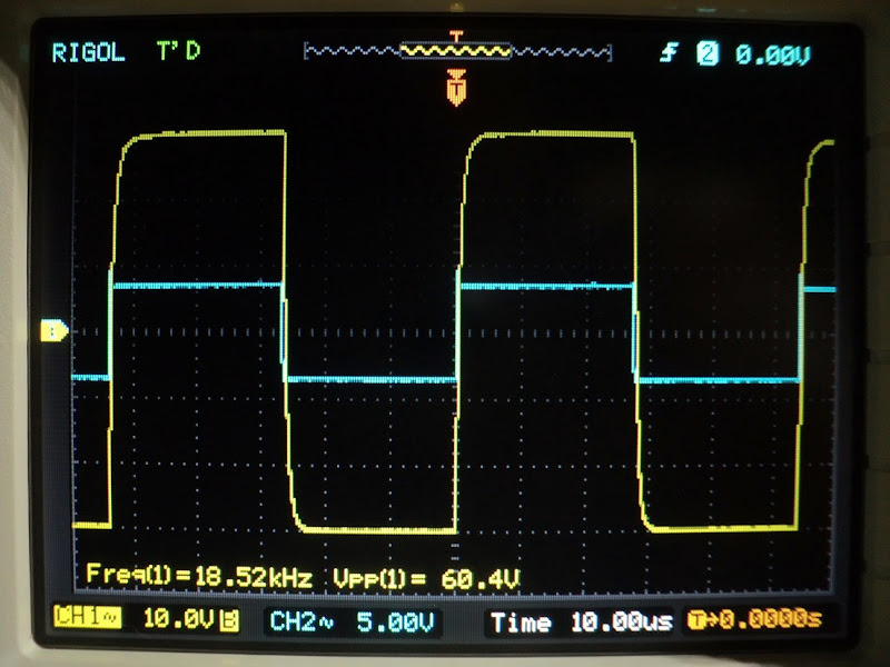
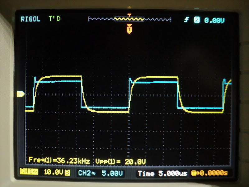
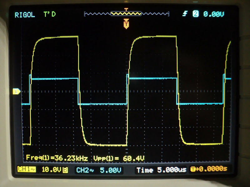
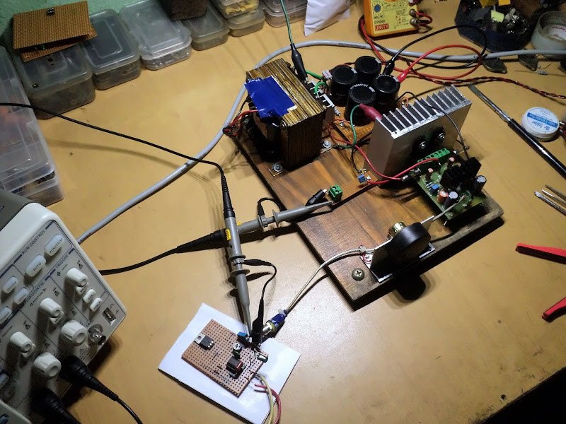
So, just got a scope and these are a few initial shots of a PeeCeeBee fed 18Khz and 36Khz uncleaned squarewave from a 555 timer, taken at 20Vp-p and 60Vp-p (check attached pix, blue - 555 timer output, yellow - amp output). Biasing is done (still) by two 15K resistors. Hum at output is less than 5mV and DC offset is 22mV without any tweaks. No load is connected to the amp and output zobel is disconnected. Two 22pF as Cdom is installed as the amp oscillates at 8Mhz as soon as the zobel is disconnected (with zobel installed it doesn't need comp caps, checked.). Input is 1K/100pF filtered and VAS current is 11mA. MOSFET biased by two series 1N4148 in parallel with a 1000uF/6.3V cap. PS is +/-35V with CRC of 6800uf+1R(2W)+6800uF.

The original thread link is here: PeeCeeBee - diyAudio

I plan to print a bunch of these boards with single and double MOSFET outputs and a few modifications (like two-bjt CCS) and some other additions suggested by people over-time. I am also going to print the double MOSFET V2 boards shared in post #1011 of the original thread. So keep an eye on the index if you are interested :).

p.s. - feel free to suggest torture tests, I am ready to burn a few boards. :D
thanks.
shaan

1.JPG


2.JPG


3.JPG


4.JPG


6.JPG


5.JPG
 
Hi All.

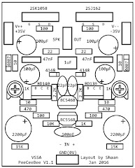
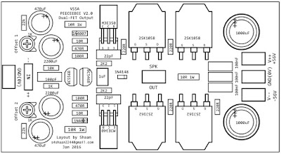
Three layouts of PeeCeeBee have been prepared for batch printing. The component placement have been shown below.

1) V1.1, a mod on the the original PeeCeeBee with corrected silkscreen, better grounding, zobel, Cdom and better offset control for 100W into 4R with +/-35V.
Size - 2"x2.5"

v1.jpg

2) V2.0, a double MOSFET version with better offset control and lower bias per MOSFET, zobel, Cdom and separate input ground header for 250W into 4R with +/-56V.
Size - 4.6"x2.5"

v--2.jpg

3) V3.0, a compact version with better offset control, zobel, Cdom, separate input ground header and horizontal MOSFET placement on opposite sides of board for 100W into 4R with +/-35V.
Size - 2.2"x2.2"

v3.jpg

All three variants are going to have direct coupled input and output. With 2200uF feedback caps the -3dB low frequency response is 1.1Hz and unity gain at DC. Board material will be 2mm FR-4 with 70mircon copper. The plans will be sent to printer next week after thorough checkup for layout errors.

.shaan
 
Last edited:
Hi Saheb.

My plan is to provide bare PCBs and fully assembled and tested boards.

edit - I don't have any boards of the last version left.
 
Its Looking Good ... Can you send me the Price of Bare PCB in my Inbox for Single Version 100 Watts. I am Having 2 Pairs of these Mosfets may be i could use them with these PCB's.
 
Hi Sadik.

The PeeCeeBee boards will be home between 15 and 20 Feb.

News!!!
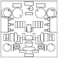
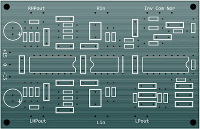
I have completed a 2.1 channel fixed frequency (i.e. customizable but not variable frequency) LR24 crossover board layout with low-pass phase switch for use with these amplifiers (or any other amplifier). This board will use one Dual and two Quad opamps (10 units total), 22 capacitors (including signal and decoupling capacitors), 30 resistors and one jumper on a single sided board. It represents a strip-board design done mid last year. The strip-board layout was built three times total (one for myself and two for a local friend). All of these are working well without problem so I decided to make a more approachable version of it.

Here is the plan at a glance. The layout will be shared in a different thread. Size 8cm x 5cm.

xover.jpg

And the strip-board version.

DSC04318.JPG
Cheers!
shaan
 
Shaan excellent work.
I suppose there is a buffer in front of each channel for impedance matching?

I also use the one 24db fixed value active crossover and two 12db of the same kind.
 
Hi Saheb.
Thanks.
The dual opamp is used as buffer for the input channels. Left opamp is the high pass section, similar in top and bottom. Top-right consists of the channel mixer, a 6dB/octave HF filter, sub-woofer phase switch and subsonic filter. Bottom right is the low pass X-over.
 
Do you use a phase reverse in conjuction with the un phased out to get a bridged sort of out for lowpass x-over?

The sum of the two buffer output is connected to the "Com" terminal, with two 10K series resistors and a 1nF to ground so that there is minimal crosstalk between the high-pass channels. From here an SPDT or sliding switch connects this terminal to either of the "Norm" and "Inv" terminals. The "Norm" terminal connects to the +in pin of the opamp and the "Inv" terminal connects to the -in pin. The +in pin is biased to ground via a 10K resistor, the -in has a 10K series resistor and the resistor from -in pin to out pin is also 10K. In this configuration we can use the opamp unit as either a non-inverting or an inverting buffer, depending on which of the "Norm" and "Inv" terminal the switch is shorting to the "Com" terminal. The input impedance of both +in and -in pins are nearly equal.

The non-inverting/inverting phase switch is after the channel mixer and before the sub-sonic filter and corrects the phase before the low-pass crossover section which has the same phase response as the high pass section when the switch is in non-inv mode as these are all 24dB/octave filters.

The low-pass out is not bridged or balanced, the signal at its input is single ended(from the subsonic filter) and the low-pass out is a simple opamp output through a 100ohm resistor. The "Inv" mode and the sub-sonic filter does change the phase response of the signal and this is why a phase switch is implemented.
 
Last edited:
The sum of the two buffer output is connected to the "Com" terminal, with two 10K series resistors and a 1nF to ground so that there is minimal crosstalk between the high-pass channels. From here an SPDT or sliding switch connects this terminal to either of the "Norm" and "Inv" terminals. The "Norm" terminal connects to the +in pin of the opamp and the "Inv" terminal connects to the -in pin. The +in pin is biased to ground via a 10K resistor, the -in has a 10K series resistor and the resistor from -in pin to out pin is also 10K. In this configuration we can use the opamp unit as either a non-inverting or an inverting buffer, depending on which of the "Norm" and "Inv" terminal the switch is shorting to the "Com" terminal. The input impedance of both +in and -in pins are nearly equal.

The non-inverting/inverting phase switch is after the channel mixer and before the sub-sonic filter and corrects the phase before the low-pass crossover section which has the same phase response as the high pass section when the switch is in non-inv mode as these are all 24dB/octave filters.

The low-pass out is not bridged or balanced, the signal at its input is single ended(from the subsonic filter) and the low-pass out is a simple opamp output through a 100ohm resistor. The "Inv" mode and the sub-sonic filter does change the phase response of the signal and this is why a phase switch is implemented.

Okay, got it.
Are these pcb(s) going for fabrication as well ?:licklips:
 
I hope the dishes will bring pleasure. ^_^

Edit:
The PeeCeeBee boards will be supplied with schematic, gray-scale picture of layout and silkscreen overlapped and an assembling and power-up guide for ease of building.
 
Last edited by a moderator:
Hi Shaan.

I have downloaded the PCB from diyaudio.com from your thread and have made 2 PCB ready. I just need some clarifications.

Toroidal I will be using is 35 0 35 Vols 200VA.
Bank will be 22000 uf 63V x 2 Nos.
DC Voltage measured is around 47 V

Will this Power Supply suitable for this PEECEEBEE.

Secondly on the offset (OFF1) should I use Jumper or should I add a specific resistor. If I have to add resistor what will be its value. Sorry for this stupid question because I am not master in this Field. I am just trying to learn by my own way.

DIY PCBs made by me & Photos of same are on my google Drive and below is the link.
https://drive.google.com/open?id=0B2a9DN9GbmtBeFgtc2pxbzhBQUk

Sadik Bhatkar
 
Hi Sadik!

Nice to see you are DIYing it the way it was meant to!

With the default BJTs the maximum safe DC voltage is +/-35V. For it to work safely at 47V you will need BC556B/546B input pair and MJE340/350 VAS pair and increase the 15k resistors to 27k.

For the OFF resistors use 330K resistors. These resistors are in parallel with the 15K resistors and are used for fine tuning only the offset. If you match the input pair and VAS pair to within 50 units then it is possible that you won't need the OFF resistors. Careful, placing a jumper across the OFF markers will cause the amp to EXPLODE violently.

A few tips:
1) Remove the 470ohm near the output terminal.
2) Replace the film caps near the supply terminals with 100uF electrolytics while taking care of pin polarity (the minus pins should face the +supply, don't worry the connections are correct underneath the board).
3) Use 2200uF/6.3V good quality electrolytics in place of 1000uF.
4) Place the VAS bjts so that their metal backs face the input section.
5) Use a non-polar electro as the input 10uF capacitor.
6) Connect speaker return directly to PS ground and not on the PeeCeeBee board ground.
7) If oscillation occurs even when a zobel or a load is connected then install a 22pF ceramic from base to collector of each VAS bjts.

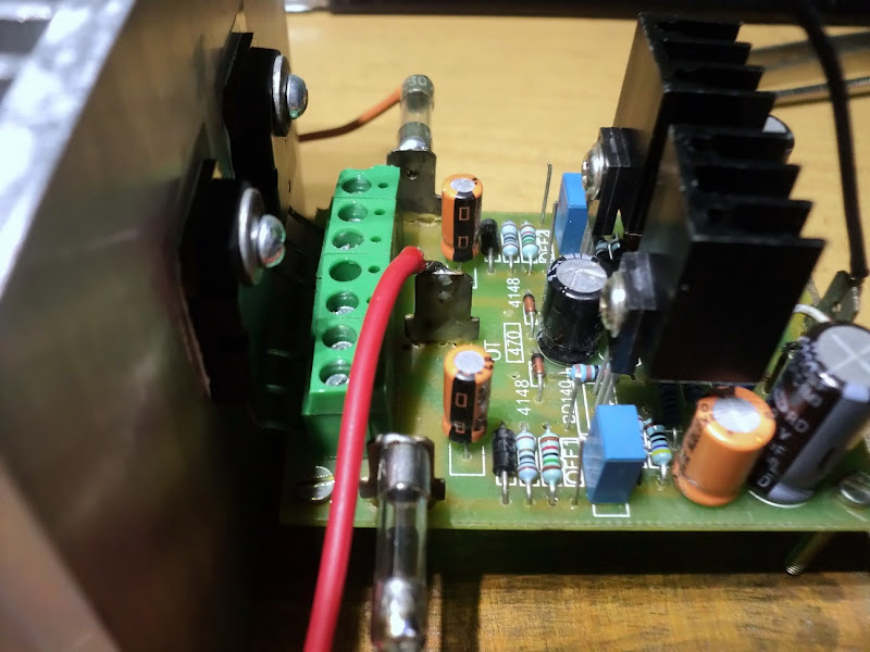
Here is a bigger photo that might be useful.

DSC00800.JPG

All the best!
shaan
 
Last edited:
The Marantz PM7000N offers big, spacious and insightful sound, class-leading clarity and a solid streaming platform in a award winning package.
Back
Top