Hello Friends!
First of all, Happy New Year!
Now,
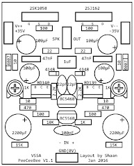
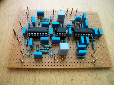
You may or may not heard about VSSA, the Very Simple Symmetrical Amplifier popularized on the diyAudio forums by LazyCat. But a couple year ago I designed and printed a layout of one of the simplest versions of the amplifier that is called the "PeeCeeBee" and since then a couple of the boards are sitting in my main system without any change. And after 2 years, I feel like nothing has changed. It sounds good.
The original layout has been tried by many people and in general the amp has worked flawlessly without dominant pole compensation, which was surprising for those who use it, including me; a three stage amp has quite a lot of phase lag right? Well of course it does, but the device intrinsic capacitance and higher value feedback resistors were "just" keeping it from getting too excited about itself.
Many people has tried and tested this layout of this amplifier, with mostly encouraging results. However, all I could do was to guess, here and there. My system sounds real nice but I didn't know if there is anything funny going on in the upper band of it's frequency response, though the input has some RF filtering.
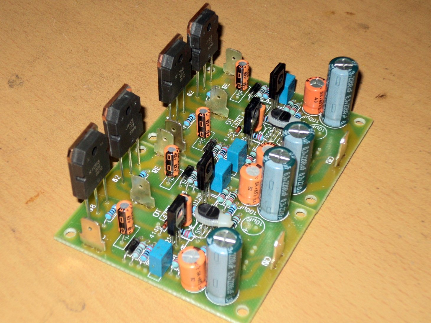
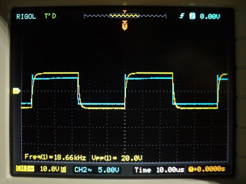
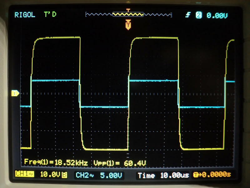
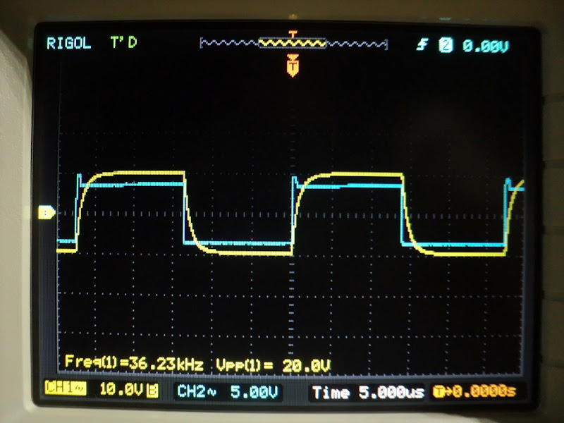
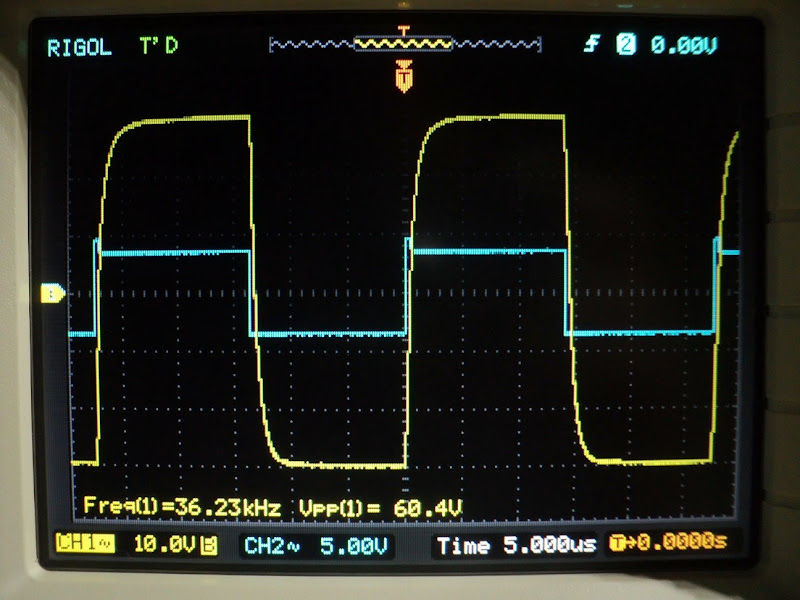
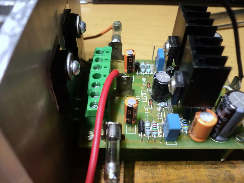
So, just got a scope and these are a few initial shots of a PeeCeeBee fed 18Khz and 36Khz uncleaned squarewave from a 555 timer, taken at 20Vp-p and 60Vp-p (check attached pix, blue - 555 timer output, yellow - amp output). Biasing is done (still) by two 15K resistors. Hum at output is less than 5mV and DC offset is 22mV without any tweaks. No load is connected to the amp and output zobel is disconnected. Two 22pF as Cdom is installed as the amp oscillates at 8Mhz as soon as the zobel is disconnected (with zobel installed it doesn't need comp caps, checked.). Input is 1K/100pF filtered and VAS current is 11mA. MOSFET biased by two series 1N4148 in parallel with a 1000uF/6.3V cap. PS is +/-35V with CRC of 6800uf+1R(2W)+6800uF.
The original thread link is here: PeeCeeBee - diyAudio
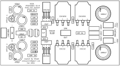
I plan to print a bunch of these boards with single and double MOSFET outputs and a few modifications (like two-bjt CCS) and some other additions suggested by people over-time. I am also going to print the double MOSFET V2 boards shared in post #1011 of the original thread. So keep an eye on the index if you are interested") .
.
p.s. - feel free to suggest torture tests, I am ready to burn a few boards.
thanks.
shaan
First of all, Happy New Year!
Now,
You may or may not heard about VSSA, the Very Simple Symmetrical Amplifier popularized on the diyAudio forums by LazyCat. But a couple year ago I designed and printed a layout of one of the simplest versions of the amplifier that is called the "PeeCeeBee" and since then a couple of the boards are sitting in my main system without any change. And after 2 years, I feel like nothing has changed. It sounds good.
The original layout has been tried by many people and in general the amp has worked flawlessly without dominant pole compensation, which was surprising for those who use it, including me; a three stage amp has quite a lot of phase lag right? Well of course it does, but the device intrinsic capacitance and higher value feedback resistors were "just" keeping it from getting too excited about itself.
Many people has tried and tested this layout of this amplifier, with mostly encouraging results. However, all I could do was to guess, here and there. My system sounds real nice but I didn't know if there is anything funny going on in the upper band of it's frequency response, though the input has some RF filtering.
So, just got a scope and these are a few initial shots of a PeeCeeBee fed 18Khz and 36Khz uncleaned squarewave from a 555 timer, taken at 20Vp-p and 60Vp-p (check attached pix, blue - 555 timer output, yellow - amp output). Biasing is done (still) by two 15K resistors. Hum at output is less than 5mV and DC offset is 22mV without any tweaks. No load is connected to the amp and output zobel is disconnected. Two 22pF as Cdom is installed as the amp oscillates at 8Mhz as soon as the zobel is disconnected (with zobel installed it doesn't need comp caps, checked.). Input is 1K/100pF filtered and VAS current is 11mA. MOSFET biased by two series 1N4148 in parallel with a 1000uF/6.3V cap. PS is +/-35V with CRC of 6800uf+1R(2W)+6800uF.
The original thread link is here: PeeCeeBee - diyAudio
I plan to print a bunch of these boards with single and double MOSFET outputs and a few modifications (like two-bjt CCS) and some other additions suggested by people over-time. I am also going to print the double MOSFET V2 boards shared in post #1011 of the original thread. So keep an eye on the index if you are interested
.p.s. - feel free to suggest torture tests, I am ready to burn a few boards.
thanks.
shaan