Tracing The PeeCeeBee

Great work, Shaan.
I saw your giveaway gesture to members on diyaudio.
Truly noble act!
A big Namaste to that!!

Do you still stock boards of the previous versions?
Any options for buying as pcb, pcb plus active components, full kit?? Do mail me details when you're free.

I had "departed" from Class-AB to pure Class-A and low power sometime back. But the very positive experiences of the many builders have prompted me to warm up my soldering iron once again and taste some modern AB goodness. ( I'm a senior citizen!)

It is people like you who make this world go round... pleasantly humming along!!

--UKP
 
I feel that the 90s were the heyday of Elektor amplifiers. Those MT-200 packages! Seeing the A1216/C2922 always makes me happy.
Again, thanks for the link.
Cheers,
~HP
 
With permission from Shaan, would like all to know that I have a pair of peeceebee v4 rev1 modules tested and packed by him for sale. Kindly check out my post in the For Sale By Owner thread on hifivision. Thanks!
 
Hi Shaan, I'm new to diy n have never done it neatly before. Hence my question... Do you have pre assembled kits? With all components including toroidal and psu... All pre soldered...? Please PM me with total cost... Very interested.

(In the past, I had one of our members send me an assembled super simple preamp)

thanks...

Hi Duncan.

V4 and V4H pre assembled modules available now. I will PM you cost details shortly.

Power supply modules will be available in late October.

You can buy the transformer from torotrans.com. They make quite nice toroidals.

I am sorry but I don't ship fully built amplifiers by courier, only local pickup from home by buyer.

Thanks
 
Hi Shaan, I'm new to diy n have never done it neatly before. Hence my question... Do you have pre assembled kits? With all components including toroidal and psu... All pre soldered...? Please PM me with total cost... Very interested.

(In the past, I had one of our members send me an assembled super simple preamp)

thanks...

I can help you with assembly and cabinet.
 
Was fortunate enough to partially witness the build of peeceebee v4 done by @jls001
There were few major hiccups with the build but it all got solved and today Joshua was about to fire it up and I was in his area
Heard few tracks with which I am familiar with and this amp impresses right off the bat.
Big bold sound, but not overly thick sound. Excellent tuneful bass.
Overall tonality is very balanced but equally musical
I had read it's a very clean sounding amp but frankly never expected it to sound so bloody good. Genuinely a superb sound. I now wish Joshua would have made two monoblocks :)

I am sure Joshua does not need his class A amp more

@shaan very good deisgn by you
Don't understand anything about amp deisgns but the final sound is very impressive and even more when we know no exotic part is recommended for this build

Also Joshua has taken lot of pain to make the build as clean as possible and it's really we'll made by him

In the end a superb outcome
 
Here's a pic of the PeeCeeBee v4 build:

PeeCeeBee V4 Built Pic.jpg

The PSU used is Shaan's PSU which is capable of using both center tapped transformer as well as dual secondary, and can be used for any rail voltage from +/-20V to +/-56V. My transformer is center tapped, 24-0-24V so rectified rails are about +/-36V which is well within the SoA of the VAS pair of MJE340/350 BJTs (BD139/140 is limited to about +/-35V). I don't remember the exact VA rating of the transformer but it was sufficient for the 50W MyRef Rev C amp. The PSU includes a full-featured speaker protection circuitry and therefore has a high parts count and is fairly complex to put together.

PeeCeeBee V4 details here.

The small cabinet made my build very difficult. The cabinet was tailor-made for the MyRef Rev C whose boards are compact because they had the PSU (including the large caps) built into the mono amp boards and the space inside was comfortable (though certainly not large) for a stereo pair with the transformer. Since I could not get one channel of MyRef amp working after it failed on me for the last time, I thought it was time to re-purpose it. The two cuts on the front side horizontal beam (visible at the bottom of the pic) were necessary to be able to plug/unplug the Vcc and Vee wires from/to the PSU, and to accomodate the transformer. A Bosch angle grinder with cut-off wheels came in handy for the purpose.

The actual build was full of accidents and incidents. I managed to blow a few components due to a mistake I made in mounting the screw for 2SK1058 n-channel power MOSFET.

PCBv4 PCB.png

Q11 and Q12 are the power transistors for the amp and both have a hole in the board for the mounting screw. The hole --- as can be seen in the pic --- is surrounded by a "ring" which is metallic. On Q11 (K1058 lateral MOSFET), the screw for bolting the MOSFET somehow shorted the Drain of the MOSFET to the chassis. Q12 was mounted similarly but no shorting happened. This mistake blew a few components - a resistor in the path of the Vcc and an LED but extended my build no end. In case you get a very high DC offset of about -18 to -19.x Volts you can be fairly sure that your screw is shorting the n-channel MOSFET to the chassis. If it's a +ve DC offset it's probably the p-channel. Shaan was there to offer guidance at every step. Kudos to him! Luckily no semiconductor blew. The one good that came out of this episode was I ended up inspecting every component closely and testing all small signal BJTs, diodes and LEDs.

Once the boards powered up properly it was a breeze to bias the VAS, set the DC offset and bias the MOSFETs (I think I may have biased it a bit high for my small heatsinks).

So far I have played about 5 CDs only so it's early days yet to critically judge the sound but I agree with Rikhav's preliminary impressions. I will write more after it gains more hours.

Right now I am enjoying a Steely Dan CD:)
 
Was fortunate enough to partially witness the build of peeceebee v4 done by @jls001
There were few major hiccups with the build but it all got solved and today Joshua was about to fire it up and I was in his area
Heard few tracks with which I am familiar with and this amp impresses right off the bat.
Big bold sound, but not overly thick sound. Excellent tuneful bass.
Overall tonality is very balanced but equally musical
I had read it's a very clean sounding amp but frankly never expected it to sound so bloody good. Genuinely a superb sound. I now wish Joshua would have made two monoblocks :)

I am sure Joshua does not need his class A amp more

@shaan very good deisgn by you
Don't understand anything about amp deisgns but the final sound is very impressive and even more when we know no exotic part is recommended for this build

Also Joshua has taken lot of pain to make the build as clean as possible and it's really we'll made by him

In the end a superb outcome

Hi Rikhav.

Thanks for the kind words.
Development of the v4/v4h amps took a lot of time and effort. So I am grateful for all the appreciation and support from the DIYers; keeps me going. :)
 
Here's a pic of the PeeCeeBee v4 build:

View attachment 30460

The PSU used is Shaan's PSU which is capable of using both center tapped transformer as well as dual secondary, and can be used for any rail voltage from +/-20V to +/-56V. My transformer is center tapped, 24-0-24V so rectified rails are about +/-36V which is well within the SoA of the VAS pair of MJE340/350 BJTs (BD139/140 is limited to about +/-35V). I don't remember the exact VA rating of the transformer but it was sufficient for the 50W MyRef Rev C amp. The PSU includes a full-featured speaker protection circuitry and therefore has a high parts count and is fairly complex to put together.

PeeCeeBee V4 details here.

The small cabinet made my build very difficult. The cabinet was tailor-made for the MyRef Rev C whose boards are compact because they had the PSU (including the large caps) built into the mono amp boards and the space inside was comfortable (though certainly not large) for a stereo pair with the transformer. Since I could not get one channel of MyRef amp working after it failed on me for the last time, I thought it was time to re-purpose it. The two cuts on the front side horizontal beam (visible at the bottom of the pic) were necessary to be able to plug/unplug the Vcc and Vee wires from/to the PSU, and to accomodate the transformer. A Bosch angle grinder with cut-off wheels came in handy for the purpose.

The actual build was full of accidents and incidents. I managed to blow a few components due to a mistake I made in mounting the screw for 2SK1058 n-channel power MOSFET.

View attachment 30461

Q11 and Q12 are the power transistors for the amp and both have a hole in the board for the mounting screw. The hole --- as can be seen in the pic --- is surrounded by a "ring" which is metallic. On Q11 (K1058 lateral MOSFET), the screw for bolting the MOSFET somehow shorted the Drain of the MOSFET to the chassis. Q12 was mounted similarly but no shorting happened. This mistake blew a few components - a resistor in the path of the Vcc and an LED but extended my build no end. In case you get a very high DC offset of about -18 to -19.x Volts you can be fairly sure that your screw is shorting the n-channel MOSFET to the chassis. If it's a +ve DC offset it's probably the p-channel. Shaan was there to offer guidance at every step. Kudos to him! Luckily no semiconductor blew. The one good that came out of this episode was I ended up inspecting every component closely and testing all small signal BJTs, diodes and LEDs.

Once the boards powered up properly it was a breeze to bias the VAS, set the DC offset and bias the MOSFETs (I think I may have biased it a bit high for my small heatsinks).

So far I have played about 5 CDs only so it's early days yet to critically judge the sound but I agree with Rikhav's preliminary impressions. I will write more after it gains more hours.

Right now I am enjoying a Steely Dan CD:)

Hi Joshua.

It was you who found out the problem that was causing the offset, so credits to You for being patient all along and setting-up the channels succesfully. :)

Cute little enclosure there. Eager to learn more of your thoughts on the amp's sonics after burn-in.

Thank you.
shaan
 
In case it is helpful to future builders, here are a few guidelines for putting together the PeeCeeBee V4 Rev 2 and Shaan's PSU:

1) If you have the Rev 1 V4 board, be sure to make the C9/C10 mod in post # 704 here. You need two 47 pF and two 220 pF ceramic capacitors rated at 500V (or higher) and two quarter watt 2K2 resistors.

2) after soldering everything on the board do crosscheck at least once that you have followed correct polarity for electrolytic capacitors, correct orientation of diodes and LEDs and used the correct small signal BJTs (BC556Bs and BC546Bs look similar and have the same physical size).

3) when ready to power it up for the first time, follow strictly the Setup guide/instructions Shaan has posted here in post #1.

4) for MOSFET biasing, the recommended resistor to be used in series with the Vcc and Vee rails is 1R/2W. None of my 2W or higher wattage resistors were exactly 1R. The closest value I measured was 1R1 so instead of the actual recommended value of 110 mV across 1R, the reading to aim for must be {Reading/1.1}. So Reading = 110 x 1.1 = 121mV in my specific case. If you're using say 1R4, you divide by 1.4, etc.

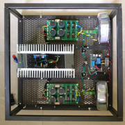
5) it's best to perform setup and biasing before final assembly as one needs access to the three 500R trimpots VR1, VR2 and VR3. So mount your amp board to heatsink, connect the Vcc, Vee, PGND connections from PSU to amp board. Connect SGND of amp board too to PGND of PSU (this is important), then power it up as per Setup instructions.

6) care must be taken while testing and setup not to accidentally touch the power rails or short them in any way (BTDT:p in both ways, and it wasn't pleasant, but it inadvertantly tested the speaker protection function of the PSU;)).

7) after you're ready to wire up everything and mount the amps to the heatsink, I would suggest insulating the screws for the power MOSFETs, and make sure that both MOSFETs and VAS transistors securely touch the heatsink through the usual thermal paste and insulating mica or nylon sheet.

8) The output signal of the amp goes to the terminal marked "IN" on the PSU board since the output to the speaker must be routed via the speaker protection circuit of the PSU. Take the positive output from "OUT" terminal of PSU to the speaker binding post (solder or screw as appropriate to your binding post). The speaker return signal to binding post must come from the PGND of the PSU. The PGND of PSU is the star ground of the entire PSU and amp circuitries.

Good to do:
1) use ground isolation circuit from equipment chassis to PGND of PSU. I use Rod Elliott's schematic, Fig 4 here. Follow the instructions on securely bolting the screw. The ground input to this isolation circuit must come from your chassis, meaning the ground lead from your IEC power inlet must first be grounded to the chassis using a bolt and washer and two bolts. This is an important safety requirement.
2) use DC loop breaker circuit. I use Rod Elliott's schematic, Fig 8 here. For 1) and 2), I use 35A bridge rectifier modules (Rs 48 per piece).
 
Some update: I've been listening to my V4 daily, may be nearly 2 hours daily, and more on some days, so it has racked up quite a few hours already. There are aspects of the sound I like and dislike. I like the paciness - there's never a dull moment. It does timing really well, and there's a sense of flow in the music. It images well and it dehomogenise the various strands of the music quite well. It occasionally surprised me with never-heard details in the music. It extends deep into both frequency extremes.

However, the quality of bass wasn't to my taste. There is a distinct bump in the upper bass, making the bass sound hard and difficult to listen for extended periods. At louder SPLs this produced a boom that was audible from adjacent rooms (but surprisingly not in the audio room). There was plenty of bass weight too.

To try and correct the upper bass hardness I repositioned my speakers to exactly one-fifth room length and one-fifth room width. This repositioning is acceptable to me as part of a change as major as a new amp. The new positioning did alleviate the bass hardness somewhat but not nearly to what I liked. I also resetted the cable doubling tweaks done in the recent past. This also helped somewhat but not fully either. I blamed it on lack of burn in and continued to listen despite my impatience.

Further, though there is plenty of highs and upper highs, I missed the airiness and delicacy.

Yesterday I had a hunch that the internal wiring I'm using for patching all DC supplies from the PSU board to amp boards, and the speaker wiring from amp board to PSU and then to binding posts, might be causing these unpleasantness. The wire is silver plated multi stranded copper with Teflon insulation. Today I changed the speaker portions of the internal wiring to tinned, multi stranded copper of roughly the same gauge to see if I can repeat my preference for tinned copper as internal wiring in phono preamps and buffers, and lo and behold, I now hear airy highs. More importantly the upper bass bump has completely disappeared, and in its place is a deeper bass than before. I'm hoping that the bass will tighten up with more hours and the nuances and texture will bloom forth.

To add: I am surely changing the rest of the internal cabling.

I totally forgot to mention that this amp is dead quiet. Zero, nada, zilch hiss or hum with ear pressed to tweeter or woofer at full volume. It's impressively quiet.
 
Last edited:
Yesterday after @jls001 changed all internal power and speaker cable to tinned copper managed to hear the amp and I was genuinely impressed

Earlier when I read about this amp design everyone mentioned it's absolutely clean sounding. I imagined it will be slightly dry sounding typically associated clean sounding amps or the way we take clean sound as per personal prefences

The new internal cabling removed the hardness in bass and sound had a good air in vocals

There are absolutely no tubes in the chain but yet the mids are it's strength or you can say the most striking feature of it's sound. The vocals have excellent sense of realism and very focused

The details are neither rolled off nor etched

For me it's the best overall sound I have heard in Joshuas setup

Some may consider the sound a little colored depending on their listening preferences but for me at least it's very natural sounding

Eager to know now what the V4H has got up it's sleeve but I know it won't happen anytime soon specially when the V4 is sounding so good
 
Wharfedale Linton Heritage Speakers in Red Mahogany finish at a Special Offer Price. BUY now before the price increase.
Back
Top