kapvin
Well-Known Member
1- To keep measurement artifact to bare minimum I did all these measurement after 11:30PM to 2:30pm to keep the mic and speakers at the same position without moving them even an um. So any artifacts would be because of other reasons beyond my control. I took many measurements ( more than 4) for each change so that it can be averaged out.
2-the wires are inside the boxes where the temperature changes will be minimum due to the isolation from the ambient.
3-ime most drivers integrate quite well in the horizontal axis SPL wise, that's why you don't get too much variation in level when you move in the horizontal axis. But most drivers where there are timing issues the SPL changes when you move in the vertical plane. If the level when you sit lower to the listening axis or in in the listening axis or when you stand up changes then it's an indication of timing issues or integration between drivers. The trick is to get them same at all listening positions in both the horizontal and vertical planes.
Time shifts causes phase errors which will increase sharpness in the highs and make the vocals very shrill asking you to reduce the volume to reduce the overlaps between drivers.
I have kept the crossover frequency in multiple of wavelength of each drivers so that any overlaps between them will add in-phase atleast at the crossover frequency.
One major point noted was earlier I needed to toe-in the speaker around 5 Deg to 10 deg to get perfect center imaging in my room. After applying the appropriate delay the toe-in is not required and the speakers are now parallel to the wall. Also the sweet spot has widened and I get the same center image in all positions in my room
Hi Hari,
That's not exactly what i meant.
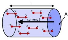
1. as per your calculation; the velocity of signal propogation through your cable material is 1400m/s (delta distance /delta time). now that's some fraction (0.0004%) of C or Velocity Factor of 0.000004. typically VF for a metallic conductor is 0.4+ in which case cable length should not make a perceptible difference. therefor the measurement night be due to the artifacts, or even due to small shift in speaker / mike. Or is there something I have missed
3. I think i should clarified more about horizontal axis. its easy enough to sum drivers of a speaker up over a longer distance. but the concern is when distance is less (like typical mumbai bedroom? where you get 6-7ft of space. that's when it becomes a challenge. vertical axis is always a challenge
best wishes
Kapil
hi, Keith, my physics is really really rusty, but delta conductance will only impact signal amplitude. Unless the conductor also has some inductance and/or capacitance, in which case there could also be a load and frequency change is amplitude and also a consequent phase shift. What hari is trying to do is reduce VF (speed of conductance) by changing the material. My very rudimentary maths tells me that even if you change VF by 99% (which is a lot) it still wont materially cause a delay of the magnitude written.Hari can you explain how one determines what specific "speed" one wants or should want for power supplies and speaker cables?
Ultimately, it all boils down to conductance which is the reciprocal of resistance. So isn't a simple answer for using a conductor (for the areas aforementioned), the highest conductance aka the lowest resistance? Or am I missing something here?
But of course, my physics is very old and very basic. So i am trying to learn here too.

")