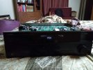
Kudos to your DIY efforts.
How do you want to have in future, completely disable the SMPS functionality ?
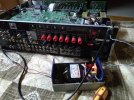
This SMPS is actually not required. Most manufacturers are doing this to get past Euro regulation norms to have very low standby power consumption. All this this SMPS does is to provide power for the standby circuit that can be switched on by pressing a button on the front panel or remote. The board also has some other use.
1. Has a relay RY371 that gets powered to a transistor Q3802 in the schematic diagram that I posted in the first post. This transistor is on a totally different board. The connection to this relay is through connector CB379. I'm not going to disable this
2. Has a power provided to an optocoupler IC375 via two 0.022 uF caps (C3701, C3717). I'm not going to disable this. See the bottom of the schematic that I posted in the first post. This also provides AC power detect to another board. This is how the microprocessor detects that the board has AC power coming in and switched on. When it detects this power, the red led on the front panel lights on.
If you want to restore your AVR back to original state, you will have to put double the efforts since you are tampering multiple components. That will become another and bigger DIY. But again, I understand that your AVR is currently not in a usable condition.
It will never be required to put the AVR to original state. By doing this, I will not lose a single functionality. But in fact, I will gain the functionality to replace the SMPS whenever it goes bad. This is like replacing your laptop power supply when the adaptor goes bad. Just because the adaptor goes bad, we don't have to throw away the laptop. So by doing this, it will be like Aug 15th 1947 for the AVR. It will get freed from the cruel clutches of a evil SMPS.
If you remove this PS1,
1. how HDMI board gets power, from main transformer ? Is it safe for HDMI board to get power directly , as these circuits are already very fragile (you see HDMI boards getting fryed for small reasons in this forum itself)
2. When you switch on main power, AVR gets ON. Any other circuits/components powered thru PS1 now gets power. Are they rated correctly .. etc etc. Just make doubly sure
The HDMI board doesn't get power from main transformer. It gets powered by 5.6 volts from this SMPS via connection board CB379. There is another board which has transistor Q3802 and which gets triggered when you press the power on button. This transistor then switches on relay RY101. RY101 relay finally switches on the main transformer which then starts supplying power to the AMP and other boards. There are multiple bridge rectifiers, regulated power supplies using 7812, 7912 and around 3 dc-dc convertors on totally different boards. The main amp gets powered via unregulated capacitor bank (+- 37 volts from the transformer and bridge rectifier). So I'm not going to fry the HDMI boards as long as I give a steady 5.64 volts (this is what this in-built SMPS is doing).
Basically I'm going to discard this complicated SMPS which provides 5.6v to the HDMI board. I have seen repair shops having charged around Rs 9000 for changing this board. I contacted the Yamaha service centre. These guys will cleverly tell you that they don't sell spare parts. They do this just because they want to fleece the customer by charging exorbitantly. In my case this SMPS has gone bad because of just one IC TOP254PN which is no longer available. The cost of this IC is less than Rs 100. Now I find that even Denon uses this TOP2xxx IC for SMPS. In most of the case where Yamaha AVRs don't switch on or give protection fault, it is because of two problems with this SMPS board.
1. This board uses 0.022 polypropylene capacitors to drop the AC voltages. They should have used resistors. But resistors reduce the voltage/current by wasting energy in the form of heat. So Yamaha is making some kind of GREEN smps by using caps. But these caps fail often. This is the most common fault found in Yamaha AVRs.
2. The SMPS itself. SMPS are always complicated because they have to switch the mains frequency and be safe enough. Over these years I have had to throw away equipment because the on-board SMPS went bad and the IC/MOSFET is no longer available. Today Yamaha/Denon/Marantz etc designs an AVR and puts in a SMPS with a chip that will no longer be available in few years. So what do you do after 10 years? Throw away the AVR? Lot of carbon, effort went into making this AVR. I just don't want to throw it away and also not give money to these authorized service centers. I would rather have drinks with my friends or donate money for some cause. How many times have your phone charger gone bad? These mosfets and switching IC fail like anything. So I'm going to replace this 5.64 volts with a LM318 regulator.


")