You are using an out of date browser. It may not display this or other websites correctly.
You should upgrade or use an alternative browser.
You should upgrade or use an alternative browser.
Help required to repair Yamaha AVR RX-V667
- Thread starter mbhangui
- Start date
Hi… I need your support. I have yamaha rx v667 and its not working. no power, no display.
if i press Power button or remote button, only i can hear quick clicking like cricky cricky and nothing happening. after searching on internet people says it is in protection mood. i tried disconnecting everything.
if i press Power button or remote button, only i can hear quick clicking like cricky cricky and nothing happening. after searching on internet people says it is in protection mood. i tried disconnecting everything.
Please go into the diagnostic mode to see the protection fault code. See this videoHi… I need your support. I have yamaha rx v667 and its not working. no power, no display.
if i press Power button or remote button, only i can hear quick clicking like cricky cricky and nothing happening. after searching on internet people says it is in protection mood. i tried disconnecting everything.
Thanks for your reply.. button combination feels like working but no display showing, no light nothing. this avr US version. 120v supply from a 220v voltage converter. my thinking its the same issue like yours. just to bypass the smps cause in the button combination mood I checked with connecting speakers it was singing .Please go into the diagnostic mode to see the protection fault code. See this video
From SMPS, i found this trick. as u can see in the picture, I just removed pin no 6. and the avr goes on normally but no front display, only HDMI to tv working. also in audio settings options become limited. but all channels and function working as it is. That pin#6 mentioned “Dest” on the board what is it for no idea. If its connect back, the avr again goes to protection mood only relay clicking but not come live.Please go into the diagnostic mode to see the protection fault code. See this video
Attachments
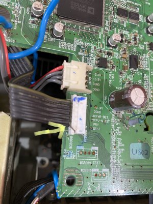
What is the voltage on DEST? Do you have a multimeter?From SMPS, i found this trick. as u can see in the picture, I just removed pin no 6. and the avr goes on normally but no front display, only HDMI to tv working. also in audio settings options become limited. but all channels and function working as it is. That pin#6 mentioned “Dest” on the board what is it for no idea. If its connect back, the avr again goes to protection mood only relay clicking but not come live.
Most likely the votage is lower. The TOP254 IC on the SMPS board would be the likely culprit. Are you using this AVR in india with the 220v to 110v converter?
I am from Bangladesh, using the avr here 2.5 yrs with the converter. sry to say I dont hv multimeter to check. and why the front display goes dead? but buttons all working.What is the voltage on DEST? Do you have a multimeter?
Most likely the votage is lower. The TOP254 IC on the SMPS board would be the likely culprit. Are you using this AVR in india with the 220v to 110v converter?
Bangladesh has proper voltage of 220v unlike here where it has been increased to 240v from earlier 230v. All new equipments getting imported in India since last 2-3 years have to certify if they work at 240v +- 10%. Else it becomes impossible to import. But AVRs purchased before 2019 may not be able to withstand current voltages in India.I am from Bangladesh, using the avr here 2.5 yrs with the converter. sry to say I dont hv multimeter to check. and why the front display goes dead? but buttons all working.
So if you have a steady voltage then nothing to worry. I was asking because the TOP254 IC used in the SMPS of v667 is designed for max of 265 volts AC. Here in india it easily gets reached. Since you are using step down convertor and even if the voltage goes high, the avr will still get voltages much below 200 volts. So most probably your TOP 254 ic should be ok.
The only way to trouble shoot at home would be to open the cover and visually inspect the SMPS board. It is mounted vertically on the left side towards the behind of the avr.
If visual inspection shows nothing unusual on the board, then you will require a multimeter to measure few voltages. The chinese multimeters are very cheap. The other option is always to give the AVR to the official service centre, but that may cost you a bit.
Your actual AVR is ok. The amp section doesn't use the SMPS. The SMPS supplies 5.5v and 3.3 volts for the digital, video, hdmi and the display unit. So the fault is somewhere in the SMPS board. Visually inspect for leaking capacitors and heat on the board. I have the service manual for 667. I can share the schematics of the SMPS board
I just went through the service manual of yamaha 667. It has two boards that are responsible for power supply to the HDMI, video and the display panel.I am from Bangladesh, using the avr here 2.5 yrs with the converter. sry to say I dont hv multimeter to check. and why the front display goes dead? but buttons all working.
The SMPS (which is for some funny reason called video2 board) supplies 5.5v
The video3 board which takes 5.5 volts from the SMPS board, converts 5.5v to 3.3 volts.
So issue will likely be in one of the above 2 boards.
Thanks for your time to write to me… i will buy multimeter as soon as possible, i checked there is no burnt/blown parts. but even i will change all caps. shortly i will update. and i hv downloaded the file for service manual. Thanks again.Your actual AVR is ok. The amp section doesn't use the SMPS. The SMPS supplies 5.5v and 3.3 volts for the digital, video, hdmi and the display unit. So the fault is somewhere in the SMPS board. Visually inspect for leaking capacitors and heat on the board. I have the service manual for 667. I can share the schematics of the SMPS board
businessbysaud
New Member
hello guys.
i have a problem.
my amp day before yesterday decided to not power up, i can see its main zone light. but when i press main zone button. nothing happens. i pressed the 3 button combo to go to diagnostic mode. but nothing happens. main zone light blinks twice and no display.
but yesterday it worked fine. started on its own.
then today it isnt starting again.
i heard a buzzing noise and i tried turning on today and no response..
any heads up? any help would be helpfull!!
businessbysaud
New Member
can you tell me what is L3701?No. The only protection this board has is the fuse and that provided by the IC TOP254N (overvoltage, thermal heat) protection. But this basic protection is present in all SMPS boards due to the danger of mains voltage coming directly to the circuit board. There is nothing extra safety feature on this board that even a basic cell phone charger has. 240 volts coming to the main board is the main reason, i have a strong dislike for SMPS. Because it is 240 volts, sometimes even a fuse will be too late to prevent a mini fire. This kind of catastrophic failure has happened to me in a iphone charger also. The charger was completely burnt inside.
The sophisticated protection features are all on the Digital board (the board with HDMI in and out sockets). It is microprocessor controlled. The voltages and currents are measured by SN74LV4051APWR IC - 8 channel analog multiplexer. Basically the pins of this two IC are fed voltages through various resistor divider network from various important portions of the boards. By removing the SMPS, I will not be sacrificing any of the protection features like high/low voltages, speaker short, over current, DC in speaker output.
To repeat, the only functions of the in-built SMPS that I'm disabling is the 5.6 volts out. The SMPS board does the following.
- To provide 5.6 volts to the digital board (HDMI board). This is what I'm disabling by removing L3701, L3702, R3712, R3710, By removing L3701, I'm cutting out the power to the SMPS portion. By removing the removing the remaining 3 components i'm disabling any extra load on the DC output.
- To provide ac detect feature through an optocoupler (I'm not disabling this)
- To provide a return path through a transistor on another board to switch on one relay. This relay when switched on, provides power to the huge main transformer. This is the transform that provides all the useful power to the AMP. I'm not disabling this connection.
my board doesnt have it. some man has DIY and bypassed it! i can show pictures of another board attached to this board
It is in the bottom middle. It is a pair of two inductors. It is for filtering the power supplycan you tell me what is L3701?
my board doesnt have it. some man has DIY and bypassed it! i can show pictures of another board attached to this board

Examine the SMPS board. The capacitors C3701, C3717, TOP254PN IC and one electrolytic capacitor near the TOP254PN IC (I have forgotten the number) are the one which mostly go bad. The buzzing sound could be the TOP254PN malfunctioning and because of that the inductors making the buzzing sound. Check the SMPS board if anything is burnt. Also check if the fuse is fine.i heard a buzzing noise and i tried turning on today and no response..
any heads up? any help would be helpfull!!
businessbysaud
New Member
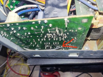
There is a really diy things done to this video2 board.
How i know whats being done here?
I need to trouble shoot. I have basic multimeter etc but will be helpfull if i gets a head start.
Anyways where is no L3701. As you can see in pictures
How i know whats being done here?
I need to trouble shoot. I have basic multimeter etc but will be helpfull if i gets a head start.
Anyways where is no L3701. As you can see in pictures
businessbysaud
New Member
Pictures attached*
Attachments
-
 IMG-20220829-WA0001.jpg161.5 KB · Views: 14
 -
 IMG-20220829-WA0002.jpg159.2 KB · Views: 14
 -
 IMG-20220829-WA0003.jpg192.3 KB · Views: 11
 -
 IMG-20220829-WA0004.jpg196.5 KB · Views: 12
 -
 IMG-20220829-WA0005.jpg153.2 KB · Views: 12
 -
 IMG-20220829-WA0006.jpg138.8 KB · Views: 12
 -
 IMG-20220829-WA0007.jpg152.9 KB · Views: 15
businessbysaud
New Member
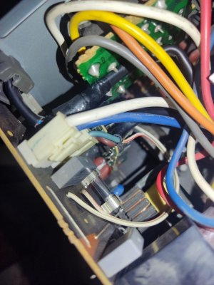
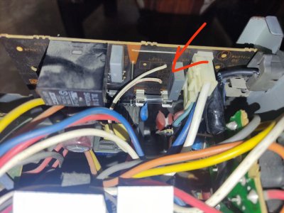
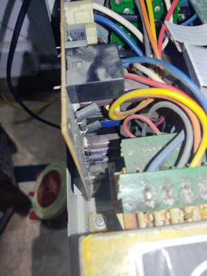
I'll check the parts tomorrow. I have attached pictures as reference to the work someone did before me.Examine the SMPS board. The capacitors C3701, C3717, TOP254PN IC and one electrolytic capacitor near the TOP254PN IC (I have forgotten the number) are the one which mostly go bad. The buzzing sound could be the TOP254PN malfunctioning and because of that the inductors making the buzzing sound. Check the SMPS board if anything is burnt. Also check if the fuse is fine.
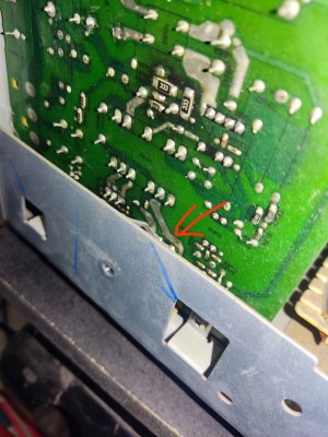
You can see L3701 is replaced with wires and its going down to another board ahich is hot glued to the video2 board. Looks legit but need to find out whats the issue now
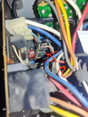
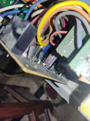
It looks like the person has installed another power supply. Removed L3701 to take the mains supply to that board. This is from picture no 5. The only job of this SMPS board is to provide 5.5v and a relay to turn on the amp. So the person who did the job has put what looks like a cell phone charger board.I'll check the parts tomorrow. I have attached pictures as reference to the work someone did before me.
You can see L3701 is replaced with wires and its going down to another board ahich is hot glued to the video2 board. Looks legit but need to find out whats the issue now
If one doesn't get that stupid IC in the market, then using another power supply is the best thing to do. So the person has taken the mains supply to another board and taken the 5v output from that board and soldered the output on the yamaha SMPS board where 5.5 volts is supposed to be there. In fact this is what I did before I got the IC.
Last edited:
businessbysaud
New Member
This will cause the reciever to not turn on?It looks like the person has installed another power supply. Removed L3701 to take the mains supply to that board. This is from picture no 5. The only job of this SMPS board is to provide 5.5v and a relay to turn on the amp. So the person who did the job has put what looks like a cell phone charger board.
Like main on button does nothing. If i press tone+info+power. The reciever blinks red light twice. And then stays off.
Is this MOD culprit or something else is bugging?
Buy from India's official online dealer!
Similar threads
- Replies
- 2
- Views
- 10K
- Replies
- 10
- Views
- 14K
- Replies
- 5
- Views
- 9K