Hiraga Le Monstre build on the anvil

GeorgeO

Well-Known Member
Joined
Jul 14, 2009
Messages
4,176
Points
113
Location
Cooke Town Bangalore
As Bijin and others have already (and admirably) documented their builds of this amp, I wont go down the same path. By all accounts it offers a good bang for the buck. Boards with components are available either on Ebay ( Jims audio is one such) or others. Toroidals are locally available from multiple sources, and so are cabs. I expect cost will be around 22-23k, am aiming for around 12 watts Class A, and plan to mate it to my Altecs. Will post again after making significant progress, hope to complete it in the next 4-6 weeks.

My thanks to all FMs who have built/plan to build this amp for their constructive suggestions and advice. For more serious people wanting to know more about how to build this amp, there is a 130 page thread on diyaudio as well as a few threads here, please spend some time reading them-I did!
 
Ive got the components ready, PCB soldered, mains toroidal in hand as well as RCAs and binding posts ready. I've been a bit busy with some personal travel and not had time to make progress. I am exploring some local options for the chassis( logistically easier), and will post after I have made a bit more progress-for now I am in a holding pattern, waiting for some bits and pieces to fall in place. In the event this doesn't get completed by next week, then there will be a little more delay because I may be tied up with some other commitments.

Will update.
 
Re: Hiraga Le Monstre built

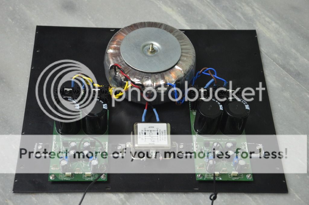
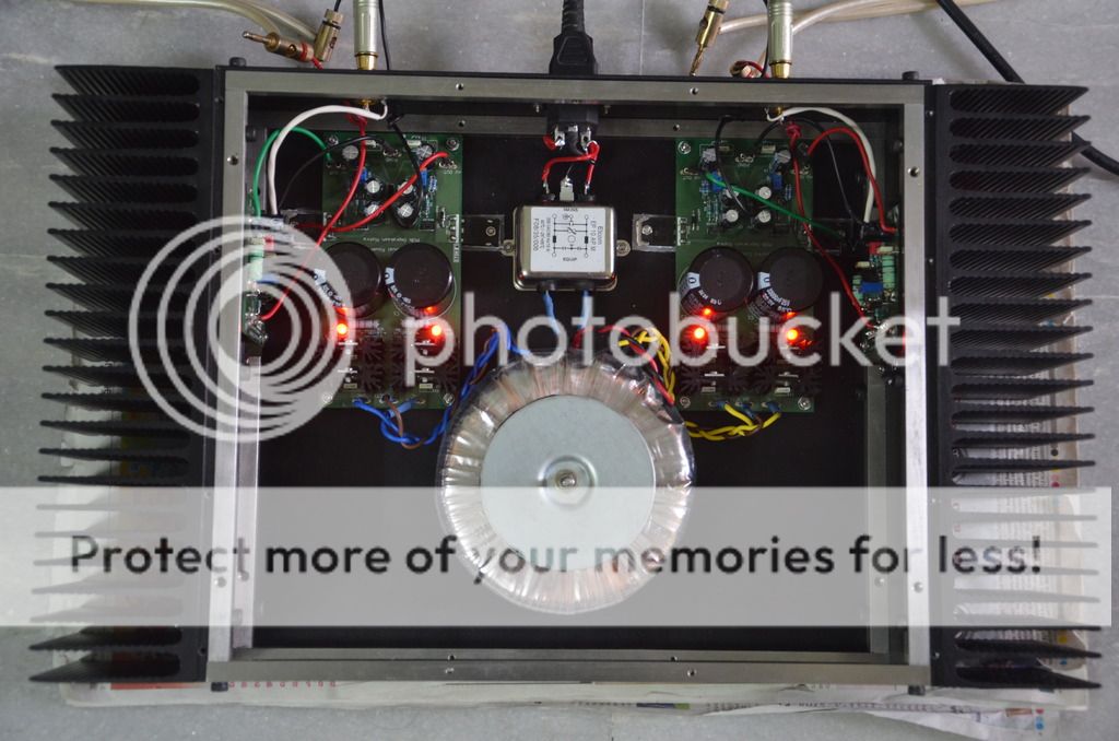
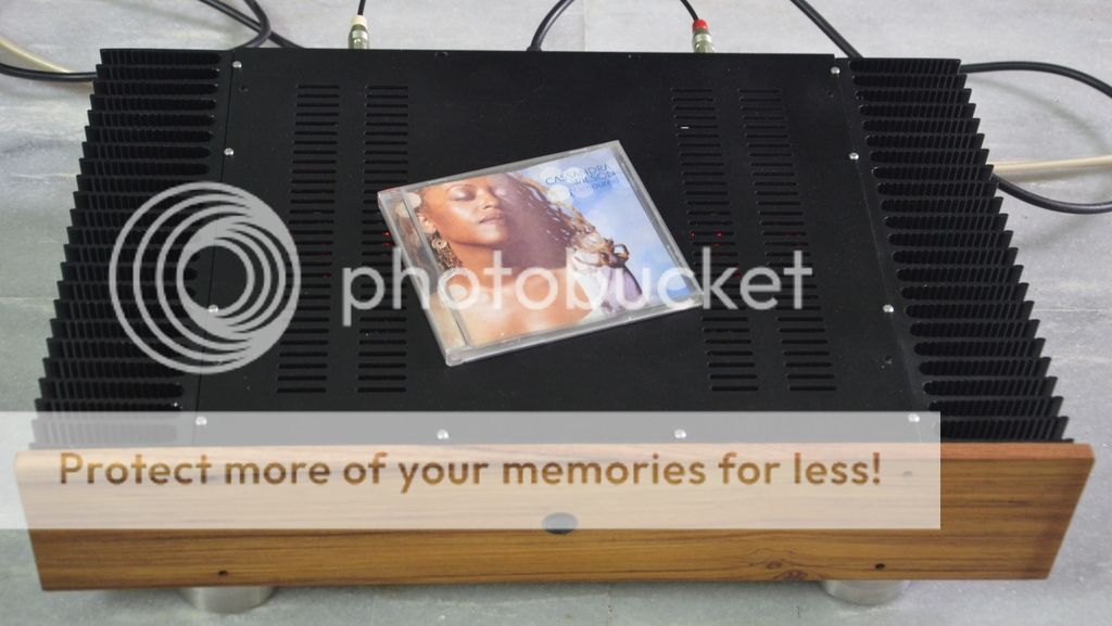
We were working on this amp since 8 months. Raghu has completed first amp yesterday night. He has sent me few pics and audio clips. Amp is running continuously since yesterday night. It is running warm, all transistors are running warm. This has very good gain and sound quality is very good.
I must add that PCB layout is excellent. Omishra has done superb job with this layout. Grounding scheme is very good and it runs without any hum, hiss etc. We are using cap multiplier Power supply. Amplifier is biased for 1A. DC offset is adjusted below 5mv.
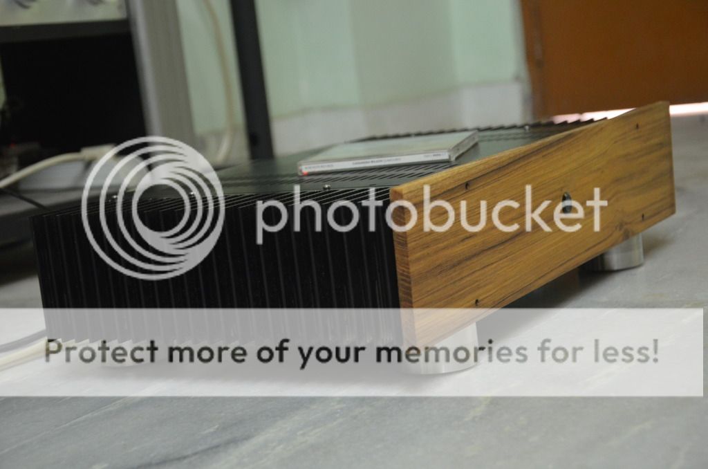
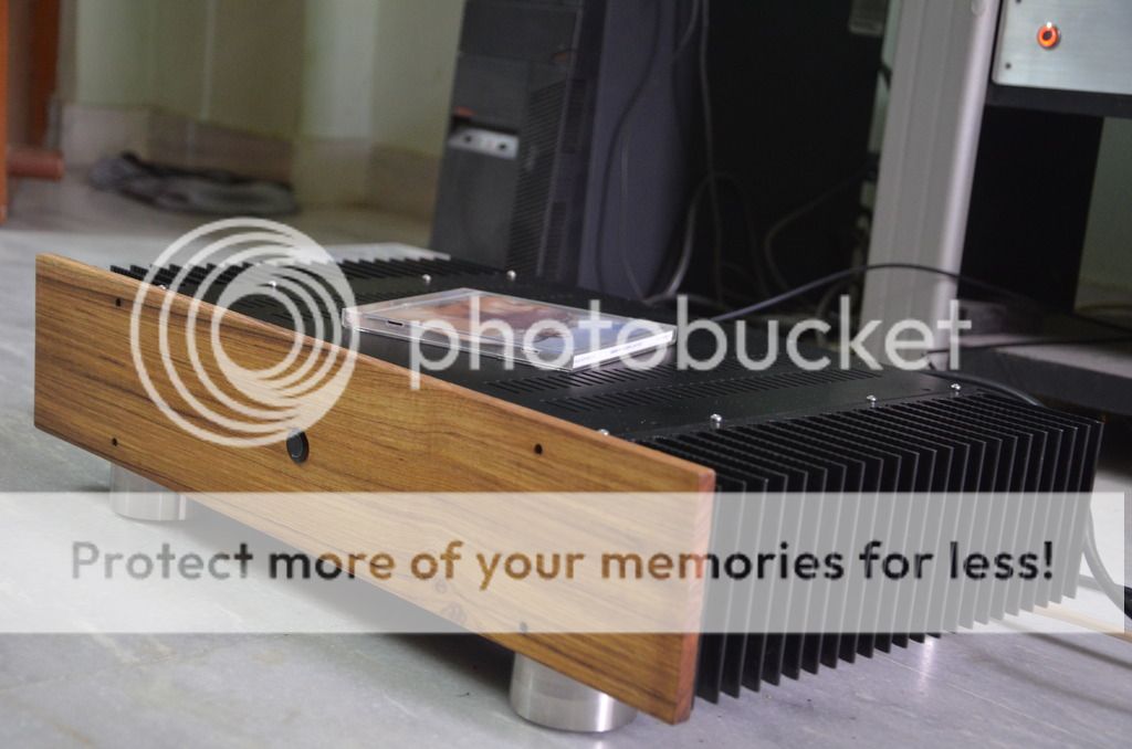
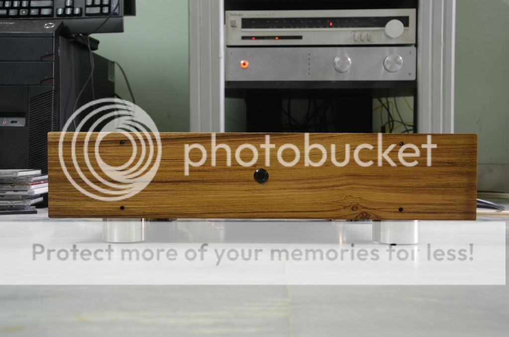
Raghu has built very good quality all Aluminium Cab with thick Teak wood faceplate.
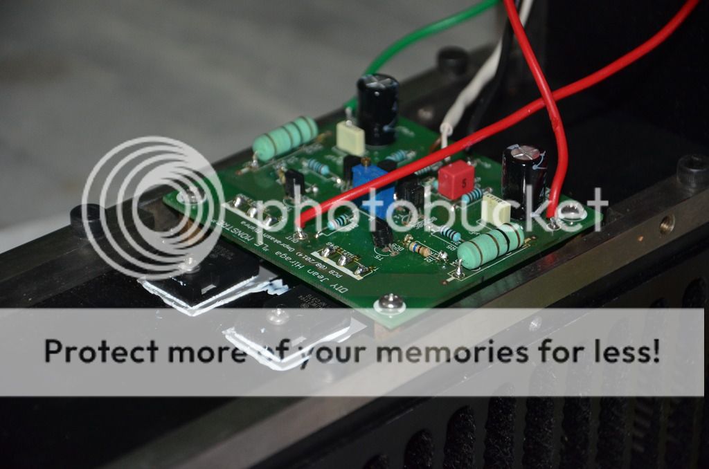
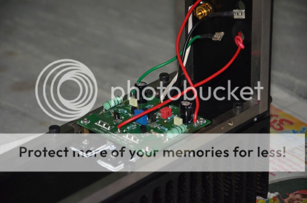
Here are some pics:


Faceplate is still raw and feet are temporary. It will look much better after final finishing.

Regards
Sachin
 
Last edited:
Congratulations on a wonderful build!

If it were me I would change 3 things. 1. The faceplate screws - Use some big headed allen bolts with half the head countersunk. 2. The feet - make them stubbier (shorter). 3.The faceplate corners - round them.
 
Congratulations on a wonderful build!

If it were me I would change 3 things. 1. The faceplate screws - Use some big headed allen bolts with half the head countersunk. 2. The feet - make them stubbier (shorter). 3.The faceplate corners - round them.

Thanks Keith
Bolts are temporary and so feet. Feet are actually borrowed from Raghu's Lenco. Actual feet will be much shorter.

Regards
Sachin
 
Sachin, Omishra and Raghu great work and congrats. Happy to see another build of this little monster after long time.

BTW can you please share more information on the parts used especially the JFET's and Output transistors.

I would like to know which schematics you have followed because it has another version which uses BC550 / 560, TIP 3055, TIP 2955 and 2SK 246, 2SJ 103 JFET's.

Since majority of those components in the old design (1979 i guess) has became obsolete and available only counterfeit now a days (I believe).

It would be good if you could share some information on that part and your take on for the same.

Note: A close-up view of the assembled PCB will be fine enough to see in detail of the components used.
 
Last edited:
This is one of the best looking DIY amps - fantastic work.
Great boards from Om and Sachin, and the cabinet from our
expert, Raghu.

Faceplate - since it is wood, you can fasten it with screws from
the reverse (inside the cabinet), and avoid any visible screws on the front.
 
Thank you all.

@Bijin, please find the part values on the pcb itself
http://i1332.photobucket.com/albums/w619/sachu888/_MG_3860_zps6c998244.jpg
Initially designed for >2A bias [emoji14] which now reduced to 1A. [emoji3]
Sachin took efforts in matching transistors of NPN and PNP counterparts to nearest possible match. There are tolerances which could be nullified with preset. Also he bought all parts from reputed sources like element 14, rs india and spencors.
 
Last edited:
Faceplate - since it is wood, you can fasten it with screws from
the reverse (inside the cabinet), and avoid any visible screws on the front.

Thank you Quad,
Face plate not yet permanently fixed because of counter sink hole for mounting screws. I have to drill counter sink and power switch hole little bigger (19mm) that is why i used a cellophane tape to attach the face plate.
Om has designed very good amp PCBs and PS PCBs and Sachin provided a great parts with out compromise. I discussed with some hifi gurus (they are not active in the forum) in Hyderabad before build the amp, They advised it is good amp but it should be proper biased and power supply to be done very carefully otherwise it will give you hum and noise.It is dead quite and you can't hear any hum or noise in 0 volume, once i build this the amp it sounded like a very basic amp with pathetic sound signature. I noticed it is running almost 4 times high bias, Than bias have bean reduced to 1A at 1V
than it is sounding very good with great loudness. later have been set the offset DC voltage to less than 5mv and ran the amp almost 10hrs continuously it is sounding great with good gain, i am using 89db bookshelf speakers. The heat sinks are not heating much and i did not noticed much heat from the amp, just worming the heat sinks, I used 300 mm D x 100 mm H heat sink with 80 mm fin size. and I am using 12V DC to run the amp. in future i will increase the DC voltage to get more power. currently vocals and highs are great, bass also good but i need more bass as per my taste, i will definitely get more bass by adding the capacitors on PS.I don't have any measuring tools to test amp capability other than DMM.I can trust my ears than measuring tools, and that to it is proven design from Hiraga.

Have a great weekend
Raghunadh
 
Last edited:
Can someone share some details information on the capacitance multiplier PS board and parts used on that?
 
Great work Om, Sachin & Raghu. I happened to see the boards and chassis of George today. It's a very compact and nice design. The boards are well designed.

My only input on PCB layout is to keep the underside tracks little more thick. They are quite thin and one desolder of any component will easily lift the tracks and damage the PCB. Not for the fainthearted.

I hope to hear the sound on George's system and compare with my Pass design amps.

Cheers.
 
My only input on PCB layout is to keep the underside tracks little more thick. They are quite thin and one desolder of any component will easily lift the tracks and damage the PCB. Not for the fainthearted.

Thanks for your wishes and input.
After lot of discussed among us we decided PCB tracks and generally All components are very less current flowing <2mA, so made it that way. Other track in line of bias are thick and double side mirrors. IMO we thought tracks were enough to bear soldering torture of 10 sec.[emoji6]
Also care was taken to keep components at correct precedence in the current flow direction - from input to output, from ps rail to ground sink etc. Amp grounding scheme is key to zero hum and hiss. You see separation in signal ground and referring to mid of capacitor coupling connection using thin line.

Can someone share some details information on the capacitance multiplier PS board and parts used on that?


Keith, this power supply not secret. Just copy and paste from famous Rod Elliott design with some intelligence put into layout.
Original is here -
http://sound.westhost.com/project15.htm
I modified small thing and divided that 12K resistance into two part - one fixed and other variable for fine adjustments.
Another thing was actual layout of cap charging current and separation from discharging current done with separate thick tracks. When its gone through DC amplifier stage, now star grounding matters here with lot of ground currents are made to merge together in single point while kept separated from actual total capacitor discharging high current. [emoji3]
 
The Marantz PM7000N offers big, spacious and insightful sound, class-leading clarity and a solid streaming platform in a award winning package.
Back
Top