Making of a SMART Battery Charger

anirban420

Well-Known Member
Joined
Aug 19, 2014
Messages
302
Points
63
Location
India
Long Story Short

This thread describes the detailing of the making of a “Smart Battery Charger” for a 6-volt 5-Ah Lead Acid battery. The “Smart Charger” has three modules. Module 1 – the “Charge Module” charges the battery at its specified parameter. Module 2 – the “Sense Module” senses the battery voltage and stops charging upon its completion. It also indicates the FULL and LOW Battery status by turning on Green and Red LED, respectively. Module 3 – the “Display Module” displays the charge of the battery in the percentage scale both during charge and discharge.

The whole story is a bit long. So, I have divided it into chapters. I will post them one at a time. Discussions are welcome between them.
 
01 Some Prelude

Around 6-7 years back, I built a Battery-backed Emergency Light using a local aftermarket kit. It was backed by a locally-made rechargeable 6-volt 5-Ah Valve Regulated Lead–Acid (VRLA) battery. It powered an 8-watt CFL Lamp. According to the kit, it needed 24 hours of charging of the battery to power the CFL for around 1.5 hours. It was a happy build. However, on prolonged uses of several years, I noticed that the battery needs to be replaced after every year or so. Popular battery brands like Exide or Panasonic have stopped producing rechargeable 6-colt VRLA batteries long ago; only local made batteries are available nowadays. I have some other Emergency Lights made by the Chinese brand FIFU. These were bought in the 90s. Presently they are also fitted with local batteries. I observed that even after similar usage, they last at least for 2-3 years in those Emergency Lights.

So what was the fault? Why similar batteries do not last for a satisfactory duration after similar usage in the DIY light?

I started thinking about it. On a quick dig onto the charging circuitry of the FIFU light, I noticed that they used a constant 6-volt supply to charge the battery. On the other hand, the DIY kit not only lacks any specified charging circuitry but also charges the battery directly from the transformer after converting it to DC at a higher voltage of 12-volt. I thought that the absence of proper charging circuitry can be a key point.

In this context, I previously noticed that rechargeable Ni-MH pencil batteries also tend to last short if charged on a “Dumb Charger” that is devoid of any charge regulation. Also, unattended charging for a prolonged time reduces the battery lifetime markedly. Possibly a similar phenomenon is happening in my DIY Emergency Light that reduced the battery life.

01.jpg
 
02 A Gateway?

I started studying rechargeable batteries and their charging technologies. To my surprise, I found this topic is vast, very complex and interphases purely between Chemistry and Electronics. Battery chemistry and its associated charging electronics go hand-in-hand here. Every specific type or arrangement of batteries needs a specific charging system.

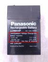
I have a couple of very old Panasonic 6-volt VRLA dead batteries; possibly they came with the FIFU lights in the 90s. They have the following two lines printed on them –

Constant Voltage Charge. Standby Use 6.8 – 6.9 V

Initial Current less than 1.6 A


I did not understand those lines for a long time. Suddenly, it opened up a new horizon of experiments in front of me. It might be a good time to start some hands-on things.

02.jpg
 
The mystery deepens, the anticipation is building up. Seriously, don’t stop.
I am waiting for the next chapter on what you found.
I must say your narration is excellent!!!!
 
03 Preparatory Phase

After the initial learning, I understood that every rechargeable battery should be charged according to its specification to optimize its life. Generally, for a single battery unit, it should be charged with a specific constant voltage and peak current limit. Often the charging voltage and the current limit depend on the charged status of the battery and these two parameters need to be changed as the charging proceeds. The charging circuitry should monitor the percentage of battery charge and change itself accordingly. A “Dumb Charger” cannot do this. Only a “Smart Charger” having a voltage sensing unit and automatic self-changing capability can supply proper power to the battery according to its status. For example, a near-empty Ni-MH pencil battery needs a robust power for initial charging having a constant current and variable voltage. After a certain amount of charging, the charger needs to switch by itself to the constant voltage mode, the charging current will vary this time. Near the charge completion, the charge should switch to a “Trickle Mode” which charges the battery very slowly, again on a constant current mode, until its full charge. The entire charging cycle of a Ni-MH battery also is dependent on its surface temperature. A temperature sensor associated with the charging circuitry should prevent it from overheating.

There is another important factor that helps to extend the life of certain types of batteries further. VRLA or Ni-MH batteries do not like over-charging or over-discharging. The charger should stop supplying power when the battery is full or the user should charge it when it is near-empty. This is one of the prime reasons for early battery failure when it is charged/discharged unattained for a longer duration.

The situation becomes more complex when multiple batteries are used inside a battery pack. In these scenarios, each battery needs to be monitored and the charge should be evenly distributed among all. Thankfully, my DIY Emergency Light has only one VRLA battery.
 
04 The Building Block

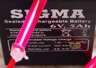
The charging parameters of a 6-volt VRLA battery are less complex than a Ni-MH battery and these were already written on the old Panasonic battery that I already have. The writings on the battery suggest that during the initial charging of a near-empty battery needs a constant current supply lesser than 1.6 A (Initial Current less than 1.6 A). However, the modern local batteries suggest limiting this current to 1.2 A (1.35 A in some models). Also, after a certain point of time the charger should supply a constant voltage of 6.8-6.9 volts until its charge is full (Constant Voltage Charge. Standby Use 6.8 – 6.9 V). A 6-volt VRLA battery does not produce any significant heat during charging omitting the need for a temperature sensor. However, both over-charge and over-discharge is fatal for these batteries. Local VRLA batteries also self-discharge easily. When kept unused, these batteries tend to self-discharge to a near-empty state within 3-4 months.

03.1.jpg

03.2.jpg

Keeping these points in mind, I planned to make a “Smart Charger” for the DIY Emergency Light. It will have three modules –

  • A “Charging Module” that will supply the battery with its specific needed power.
  • A “Sensing Module” that will sense the charge status of the battery by reading its pole voltage. It will disengage the charger upon charge completion and indicate with a Green LED. Also, it will indicate the Low Battery status with a Red LED. This module will work both for the charging and in-use (discharging) cycle.
  • A “Display Module” that is capable of showing the charge status of the battery on the percentage scale.

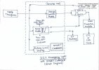
Here is the Block Diagram of the entire unit. It is shown in the “Charging” state. Upon charge completion, the “Sense Module” disengages the charger from the battery using a relay and latches it there. The latch resets after switching off the charger. The DC power of the battery is converted to a CFL/LED lamp’s usable state of AC by a “mini Inverter Module”. These modules have a straightforward design consisting of a simple transistor- and inductor-based oscillator and a basic step-up transformer. This module does not produce pure sine wave AC.

04.jpg
 
Useful literature.
Thank you. It is useful. I have read about similar Li-Ion, Ni-Cd or Ni-MH charging ICs during the preparation of the project. Unfortunately, I could not find any suitable straightforward, IC-based all-in-one solution for Lead Acid batteries. Therefore I started building my own design.
 
05 Experiment Status – ON

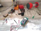
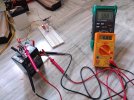
The unavailability of proper charging and discharging data of 6-volt VRLA batteries over the internet demanded studying the same. Here are some photos clicked during experimentation.

05.1.jpg

05.2.jpg

Initially, I tried but failed to charge the battery at constant voltage using the popular voltage regulator IC LM317. After several trials, it was not only unable to supply the specific power to the battery but also became too hot risking its own life. I suppose that this IC is not designed to use in such a battery charging environment. I left the idea.
 
06 The Way-Out – XL4015

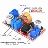
I moved to the XLSEMI Buck DC to DC Converter XL4015. It has many attractive features. Wide 8V to 36V input voltage range, adjustable output from 1.25V to 32V, constant output current capability of 5A are to name a few. It also features built-in protection against output short circuit, thermal runaway etc. Moreover, dedicated battery charging modules are commercially available using this IC. These modules feature adjustable output voltage and current capability, making them suitable for my use. Thankfully I had one such module and started experimenting with it. I noticed that it overcame all the drawbacks of LM317. It can increase the battery pole voltage smoothly upon charging without creating any noticeable heat on the IC during charging. So I took a brand new 6-volt 5-Ah VRLA battery and collected some data out of it –

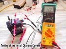
  • An over-discharged battery tends to take more than 1.5 A during the initial charge. This period lasted for about 45-60 minutes regardless of the set voltage of charger output.
  • After that, the charging current suddenly dropped down to around 0.44 A and further decreased very slowly as the charging cycle proceeded. The battery pole voltage began to increase accordingly.
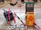
  • At the battery pole voltage of around 6.70-volts during charging, the charging current remained nearly at 0.16 A.
  • From the battery pole voltage of 6.70-volt onwards, it took a long time, almost 1.0-1.5 hr, to reach around 6.90-volt. At this point, the charging current decreased to 0.10 A.
  • The battery pole voltage hardly increased beyond 6.90-volt. At this point, using a 7.35-volt of charger output (measured while disconnecting the battery), it took almost 5 hours to reach pole voltage of battery maximum to 5.97-volt from 5.90-volt.
  • Upon disengaging the charger after charge completion, the open cell voltage (OCV) of the battery pole was at around 6.30-volt. However, it started operating at near 6.10-volt as soon as it was connected to the mini-inverter module of the Emergency Light powering the lamp.
  • It powered up an 8-watt CFL and discharged itself slowly and satisfactorily until its connected pole voltage reached around 5.0-volt.
  • Beyond 5.0-volt, the connected battery pole voltage decreased further to 4.0-volt at a moderate rate. The light was very dim at this phase.

Beyond 4.0-volt, the light did not glow at all. However, the battery continued to discharge at a slower rate. I kept the battery discharging in this stage overnight and found the pole voltage of 1.42-volt in the morning supplying 0.001 A of current. The battery OCV at this point was 3.46-volt. This might be the fatal over-discharged state of the battery I suppose.

06.1.1.jpg

06.1.2.jpg

The data indicated three things – (1) the initial charging of an over-discharged battery needs 1.2 A of constant current supply; (2) when the initial charge current decreases, the remaining charging should be done at a constant voltage; (3) since the pole voltage hardly increases beyond 6.9-volt, 6.80-6.90 volts could be considered as the full voltage of the battery. These observations were at par with the writing on the battery. I noticed another crucial point that was not mentioned anywhere before – the 5.0-volt point can be considered as the low battery status, the CFL was dim beyond this voltage.

06.2.jpg

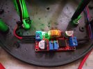
After getting the proper data of the battery, the next task of configuring the XL4015 charger module felt like an easy job. I took a 12-0-12 volt 1 A transformer to power the charging circuitry, converted the secondary output into DC using a couple to 1N4508 diode, smoothed it using 1000 μF and connected it to the input of the charger module. I installed the transformer and the charging module suitably in the available space of the Emergency Light. The next task was to set the voltage and current regulation potentiometers of the charger module. Firstly, I set the charging voltage. To do this, I disconnected the battery from its connecting terminals, switch on the charging module and set the voltage regulation potentiometer so that the terminal voltage became close to 7.0-volt. I have observed that the battery pole voltage can reach up to 6.93-volt during charging in this setup. Next, I set the initial charging current. I took an over-discharged battery and connected it to the charger via a digital multi-meter kept in series in current measuring mode. Since an over-discharged battery tends to accept a charge at higher than 1.5 A current, it was very easy to clamp it down to 1.19 A using the current regulation potentiometer of the charging module. Both voltage and current regulation potentiometers operated independently, not affecting each other’s settings. Therefore, it resulted in a happy battery charging unit.

06.3.jpg
 
07 The Self-Made Sensing Module

After a rigorous searching on the internet, I could not find a suitable sensing module that can serve my purpose. However, these are readily available for 12-volt or higher voltage batteries. So, I made one for myself.

I was looking for the following properties in the Sensing Module –

  • It should trigger twice, once for a higher voltage, other for a lower voltage.
  • It should trigger a relay and a green LED when it senses above 6.8±0.05 volts.
  • The relay should latch once triggered and reset upon switching off the charger.
  • It should trigger a red LED when it senses 5.0±0.05 volts.
  • It should be able to detect the voltage change at the resolution of 0.1-volt or lower.
  • It should be operable between 4.0-7.0 volt ranges.

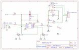
After tinkering ideas with 555 timer IC, some flip-flops, op-amps and transistors, I zeroed on LM358B Dual Comparator IC as the heart of the Sensing Module. Being a comparator, the low input offset voltage of 0.3 mV makes it fast responding. Also, it can operate at a minimum of 3.0 volts. After several rounds of experimentations, I prepared the following circuit schematic –
07.1.jpg

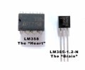
If I consider LM358B as the heart of the circuit, the LM385-1.2-N Precision Voltage Reference IC should be its brain. In practice, the LM385-1.2-N acts as a diode providing a precise reference voltage of 1.235 volts. It also consumes a very low amount of current (10 μA to 20 mA) during operation. Fundamentally, the circuit is a precision comparator that compares the scaled-down version of the battery pole voltage with the reference voltage and suitably triggers the output(s) of the op-amp during a voltage mismatch between two inputs.
07.2.jpg

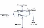
Let’s have a brief discussion about the working of the circuit. The circuit reads the battery pole voltage via the sense line. It also powers the module. The sense line is connected to the switch of the unit in such a way so that it can sense both the charging and discharging voltage of the battery.
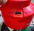
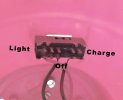
07.3.1.jpg

07.3.2.jpg

07.3.3.jpg

Each half of the LM358B detects high and low voltage, respectively. Pins 5, 6 and 7 are used for the high voltage detection. The fixed reference voltage is supplied to the inverting input (pin 6). The battery pole voltage is scaled-down using the R6 potentiometer and it was fed to the non-inverting input (pin 5). R6 sets a triggering threshold voltage for LM358B. The careful setting of R6 keeps the voltage of the non-inverting input (pin 5) lower than the inverting input (pin 6) during charging and the IC’s output remain low. As soon as the charging completes, the sensor line receives 6.8±0.05 volts from the battery pole and makes the voltage of the non-inverting input (pin 5) slightly higher than the inverting input (pin 6). This minute voltage difference between the two inputs is enough to trigger the IC’s output at pin 7 high. The non-rail-to-rail LM358B outputs around 5.5±0.05 volts at this stage. This voltage simultaneously triggers the relay and the Green LED via the driver transistor Q1 (BC548B). The R4 and R5 are the current limiting resistors for the relay and the LED, respectively. C1 prevents false pre-triggering of the LED. D1 protects the relay from back EMF. Upon the start of the transistor’s conduction, both the relay and the LED turn on. Pin 2, 3 and 5 are the switch points of the relay. Pin 3 and 5. The battery is connected to the system via the path of Pins 3 and 5 which are normally-close points of the relay. Upon conduction of the relay, it disconnects pin 3 and 5, thereby disengaging the charger circuitry from the battery. The charger is so designed that the charging terminal provides power to the “Sense Module” even after battery-charger disengagement. It keeps the relay engaged creating a latch. The latch resets and the battery terminals reconnect when the charger is powered off.

Pins 1, 2 and 3 forms a part of the low voltage detection circuitry where the fixed reference voltage is supplied to the non-inverting input (pin 3) and the scaled-down battery pole voltage is fed to the inverting input (pin 2) via the R7 potentiometer. This circuitry acts during the use of the Emergency Light when the battery discharges. The low threshold is configured in such a way that during the satisfactory charge status of the battery, it keeps the voltage of the non-inverting input (pin 3) higher than the supplied reference voltage at the inverting input (pin 2), keeping the output (pin 1) low. When the battery voltage becomes lower than 5-volt, the non-inverting input (pin 3) becomes higher than the inverting input (pin 2) driving the output (pin 1) high. The output drives the Red LED indication of the LOW Battery status until the battery voltage reduces to 3-volt. The minimum operating voltage for both LM358 and the LED is 3-volt. Therefore, the low voltage detection circuitry remains alive until this battery voltage.

During the prototype testing, the circuit reported 0.02-volt sensitivity. The means that the circuit responses at ±0.02-volt of the predefined threshold voltages. Initially, I tried several low-voltage Zener diodes, general-purpose op-amps and transistor-based circuits. But there were several drawbacks. Firstly, Zeners are not as precise as the reference diode. Secondly, they consume a lot more current than precision diode creating inefficiency during the low voltage point detection. Thirdly, the circuit works well when a low reference voltage is used; Zeners below 3.3 volts are not available. On the other hand, the general-purpose op-amps (and also transistors) decrease the sensitivity of the circuit. Their higher input offset voltage decreases the triggering precision of the circuitry.
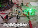
07.4.jpg
 
08 From the Prototype to a Working Model

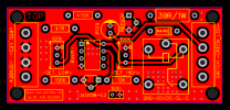
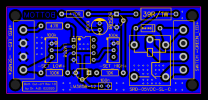
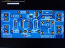
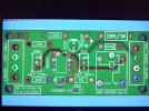
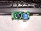
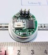
I designed the PCB in the EasyEDA online designer and etched it from PowerPCB, India. It is a double-sided board design. Here are some photographs of it.

The followings are some computer-simulated photos of the designed PCB.

08.1.1.png

08.1.2.png

08.1.3.jpg

08.1.4.jpg

08.1.5.jpg

08.1.6.jpg

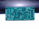
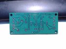
Here are the photos of the finished PCB.

08.2.1.jpg

08.2.2.jpg

I was starting to populate the PCB.

08.3.jpg

This is the photo of the PCB after component population.

08.4.jpg

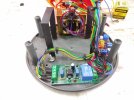
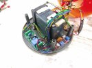
Some photos of the Emergency Light’s base after installing “Charging Module” and “Sensing Module”

08.5.1.jpg

08.5.2.jpg
 
09 Setting the Thresholds

We need two things to configure the “Sense Module” - a small wire bridge, preferably having crocodile clips at both of its ends, and a precision external variable power supply able to vary output voltage at the magnitude of ±0.05 volts or lower. The wires of the “Switch” connector should be disconnected from the circuit and joined externally via a wire bridge. Next, the variable voltage power supply should be connected to the connecting terminals of the battery after removing them from the battery pole. Use of the external power supply is optional, although it makes the task easy. Monitoring the connected battery’s pole voltage with a multi-meter can also serve the purpose. In this case, the battery needs to be charged and discharged several times to configure the module properly. It makes the process tedious and time-consuming. The charging unit should be powered on during calibration and the main sliding switch of the unit should be in “Charge” mode.

09.1.jpg

To set the high threshold, the external power supply should be set at 6.8±0.05 volts and the SET_HIGH R6 potentiometer needs to be adjusted so that the Green LED lights up. A simultaneous tripping click of the relay engagement can be heard when the LED turns on. Similarly, the external power supply should be set at 5.00±0.05 volts and the SET_LOW R7 potentiometer has to be adjusted to light up the Red LED. The threshold potentiometers need to be set in such a way that the circuit responds within ±0.05 volts for both the set voltages and it needs to be checked by varying the voltage of the external power supply. The settings should be cross-checked and readjusted finely, if necessary, at least thrice by varying the output voltage of the external power supply. After completion of the threshold settings, the “Switch” wires should be re-connected to their respective connector. A properly calibrated “Sense Module” will light up the Green LED with the relay tripped if the charger is powered on with floating battery terminals.

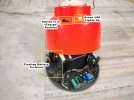
The following two short videos were taken during the calibration of the unit’s threshold. The turning on of the Green (located at the mid-bottom of the screen) and Red (located on the light’s body) LED at the preset voltage can be seen.


After assembling the base of the unit, I charge the battery until it was full. The Green LED turned on eventually, which can be seen in the following video.


Here is a photo of the calibrated unit with battery terminals disconnected. Please note that the Green LED is glowing.

09.4.jpg
 
10 The Display Module

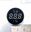
The digital voltage display module was purchased from Aliexpress. It detects a voltage range of 4-30 volts DC. It has a % scale display with user-configurable high and low scale thresholds. The module served my purpose. However, during the initial testing, it suddenly died of an accidental connection error.

10.1.jpg

10.2.jpg
 
11 The Mini Inverter Module

This is a simple module consisting primarily of two transistors, an inductor and a high-frequency ferrite core transformer. As stated previously, it is not capable of producing pure sine wave AC and can power up to 11W CFL or LED light.

11.jpg
 
12 The Ending Story

In the end, I changed the CFL to a Philips 2.7-watt LED lamp. On the full charge of the battery, it provided around 3.0-3.5 hours of light until the Low Battery Red LED kicked in. The battery took around 9-10 hours for full charge starting from a low battery state. Since the charge capacity varies in the present-day aftermarket batteries, both of these above-mentioned timings vary from battery to battery.
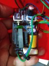
I am yet to test the long term effect of this circuit on the battery life, which was the prime concern of the project. Let’s hope for the best.

The idea of this project can be implemented to build a precision speaker protection circuitry of an audio amplifier where the protection will kick in exactly at the pre-defined DC threshold voltage.

P.S. – I am going to order a new digital voltage display module. I might update this thread after installing it.

12.jpg
 
@anirban420, I really enjoyed reading your narrative of the process even though I do not understand much of the technical bits. I think you write very well. It was like reading a suspense short story with lots of ups and downs, surprises and a happy ending. Thank you for sharing this. Hope you will do more such DIY projects. Maybe something related to audio next time ?
 
Thank you @Analogous

Yes, I try to do some hands-on things regarding DIY Electronics or Music whenever I get time besides my work. But nowadays the availability of such time is getting lesser day by day. I started this project exactly 2 yearly ago in November 2019. I did up to the PCB designing of the "Sense Module" and placed the order to China on 23rd March 2020, the previous day of the official announcement of Lockdown-I in India. My order got rejected due to the Global Pandemic situation and I have to postpone the project until the end of Lockdown-II. Recently I got the finished PCB and completed the project. However, I need to re-order the "Digital Display" module which died during testing.

The "Sense Module" has an excellent application in the audio field. Fundamentally, this module detects a DC input at the magnitude of ±0.02 mV and report it. This property can be used to design a precision speaker protection circuit which is my next plan.

Although I don't know when I can do this, I am currently having other preferences regarding hobbies.

I have posted several threads on audio in the past. You can check my account page. Alternately I can provide some thread links for your ease. upon your wish.
 
Thank you @Analogous

Yes, I try to do some hands-on things regarding DIY Electronics or Music whenever I get time besides my work. But nowadays the availability of such time is getting lesser day by day. I started this project exactly 2 yearly ago in November 2019. I did up to the PCB designing of the "Sense Module" and placed the order to China on 23rd March 2020, the previous day of the official announcement of Lockdown-I in India. My order got rejected and I have to postpone the project until the end of Lockdown-II. Recently I got the finished PCB and completed the project. However, I need to re-order the "Digital Display" module which died during testing.

The "Sense Module" has an excellent application in the audio field. Fundamentally, this module detects a DC input at the magnitude of ±0.02 mV and report it. This property can be used to design a precision speaker protection circuit which is my next plan.

Although I don't know when I can do this, I am currently having other preferences regarding hobbies.

I have posted several threads on audio in the past. You can check my account page. Alternately I can provide some thread links for your ease. upon your wish.
Yes, Please do share some of these links.
 
Join WhatsApp group to get HiFiMART.com Offers & Deals delivered to your smartphone!
Back
Top