
Jazzman53
Member
Hi All,
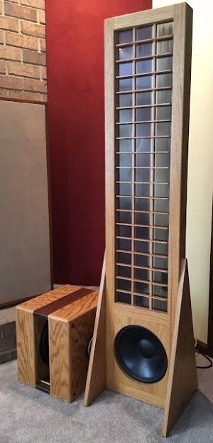
Below is my latest and probably my last ESL design, as I'm getting too old for this much work.
And forgive me if I go a bit overboard but I love talking about this stuff!
Discussions of ESL’s versus conventional speakers usually touch on their respective narrow versus wide dispersion.
Some love the ESL's tightly focused sweet spot and almost magical imaging, and others hate the beaming "head-in-a-vice" effect. Unfortunately; physics doesn’t permit having both the tightly focused magical imaging and a wide sweet spot, simultaneously.
Personally; I love being in the focus of a big pair of beaming flat-panel ESLs… but not for long periods, and not at all when guests drop by, because not everyone can sit in my lap and enjoy the magic.
Both the curved Martin Logan ESL’s and the sequentially phased Quad ESLs widen the dispersion to remedy the head-in-a-vice effect; although I prefer the Quad approach.
A lesser known but more versatile remedy for the head-in-a-vice effect employs electrically segmented stators. One commercial ESL employs a separate, narrow stator section for treble frequencies, and the King Sound ESLs have separate stator sections for the lows, mids, and highs.
Some cutting-edge ESL’s in the DIY community (including mine) employ symmetrical, multi-segmented wire stators to tailor the dispersion. This scheme is somewhat analogous to the Quad model 63 approach, with some important differences explained below.
The Quad 63 uses a separate mid/high center panel with concentric ring conductors powered sequentially thru an LC (inductor/capacitor) delay line, to emulate a point source projecting a spherical wave-front. Whereas, mine uses a vertical wire array driven thru an RC (resistor/capacitor) network to tailor the dispersion.
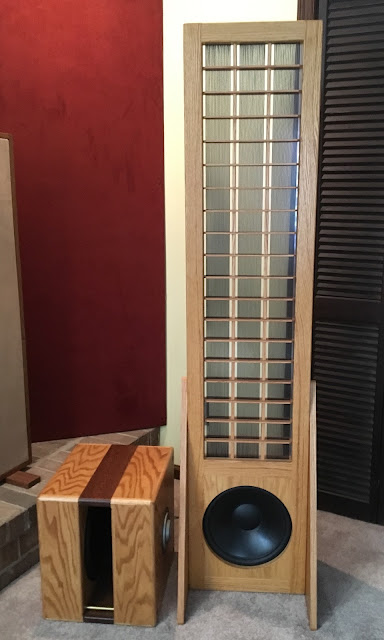
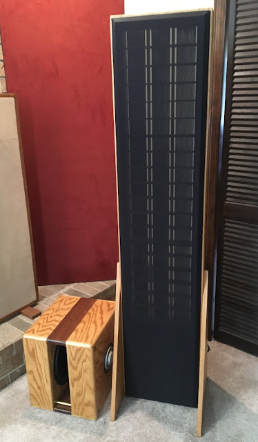
Below is a schematic of my multi-segment wire stator ESL, employing (15) six-wire groups driving the diaphragm from the center-line outward to emulate a line source projecting a cylindrical wave-front.
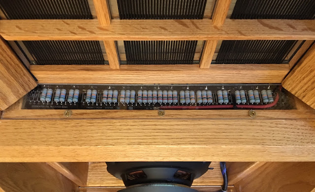
In any driver circuit, inserting a series resistor with a capacitor in parallel forms a first-order low-pass filter. In the case of a segmented ESL; the separate wire groups, coupled with the opposing/oppositely charged diaphragm, are the parallel capacitors, and we need only insert the appropriate value resistors between the wire groups to form a series transmission line of low-pass filters—as shown in the schematic below.
As driven by the segmented stators; the entire diaphragm radiates the lower frequencies, but the filter network limits the highest frequencies to only a narrow vertical band in the panel centerline, and progressively chops off the highs, moving toward the panel edges.
In addition to the progressive frequency attenuation; the charging time of the wire group capacitances imparts a progressive phase shift toward the panel edges which curves the wave front. The combined effect is wide, smooth trending dispersion, as visually depicted in the directivity sonograms shown below. The sonograms compare a non-segmented flat panel, a curved panel, and a segmented panel.
Jazzman MkIII Schematic:

Directivity Sonograms courtesy of Steve Bolser @ DIY Audio Forum:

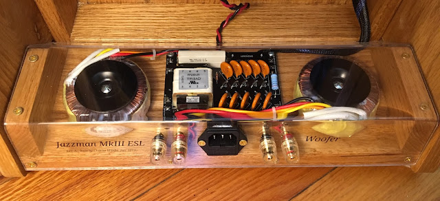
Amp Interface (step up transformers and high-voltage bias supply):
The segmentation resistor network:
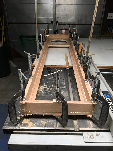
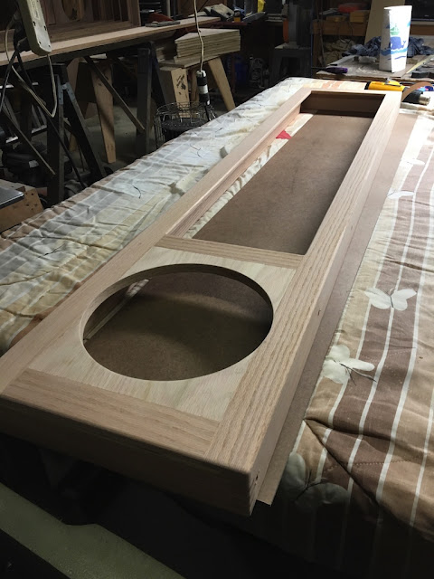
Stator in build Jig:
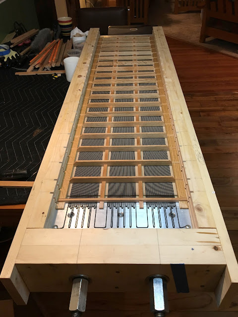
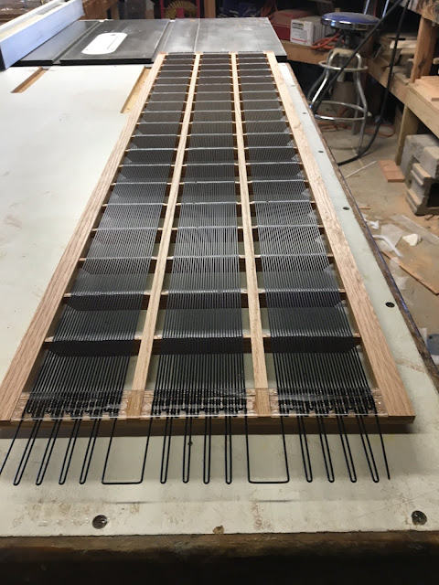
Wire Stator:
Youtube video links:
Stator Build Video
Panel Assembly Video
Jazzman MkIII Playing
Below is my latest and probably my last ESL design, as I'm getting too old for this much work.
And forgive me if I go a bit overboard but I love talking about this stuff!
Discussions of ESL’s versus conventional speakers usually touch on their respective narrow versus wide dispersion.
Some love the ESL's tightly focused sweet spot and almost magical imaging, and others hate the beaming "head-in-a-vice" effect. Unfortunately; physics doesn’t permit having both the tightly focused magical imaging and a wide sweet spot, simultaneously.
Personally; I love being in the focus of a big pair of beaming flat-panel ESLs… but not for long periods, and not at all when guests drop by, because not everyone can sit in my lap and enjoy the magic.
Both the curved Martin Logan ESL’s and the sequentially phased Quad ESLs widen the dispersion to remedy the head-in-a-vice effect; although I prefer the Quad approach.
A lesser known but more versatile remedy for the head-in-a-vice effect employs electrically segmented stators. One commercial ESL employs a separate, narrow stator section for treble frequencies, and the King Sound ESLs have separate stator sections for the lows, mids, and highs.
Some cutting-edge ESL’s in the DIY community (including mine) employ symmetrical, multi-segmented wire stators to tailor the dispersion. This scheme is somewhat analogous to the Quad model 63 approach, with some important differences explained below.
The Quad 63 uses a separate mid/high center panel with concentric ring conductors powered sequentially thru an LC (inductor/capacitor) delay line, to emulate a point source projecting a spherical wave-front. Whereas, mine uses a vertical wire array driven thru an RC (resistor/capacitor) network to tailor the dispersion.
Below is a schematic of my multi-segment wire stator ESL, employing (15) six-wire groups driving the diaphragm from the center-line outward to emulate a line source projecting a cylindrical wave-front.
In any driver circuit, inserting a series resistor with a capacitor in parallel forms a first-order low-pass filter. In the case of a segmented ESL; the separate wire groups, coupled with the opposing/oppositely charged diaphragm, are the parallel capacitors, and we need only insert the appropriate value resistors between the wire groups to form a series transmission line of low-pass filters—as shown in the schematic below.
As driven by the segmented stators; the entire diaphragm radiates the lower frequencies, but the filter network limits the highest frequencies to only a narrow vertical band in the panel centerline, and progressively chops off the highs, moving toward the panel edges.
In addition to the progressive frequency attenuation; the charging time of the wire group capacitances imparts a progressive phase shift toward the panel edges which curves the wave front. The combined effect is wide, smooth trending dispersion, as visually depicted in the directivity sonograms shown below. The sonograms compare a non-segmented flat panel, a curved panel, and a segmented panel.
Jazzman MkIII Schematic:
Directivity Sonograms courtesy of Steve Bolser @ DIY Audio Forum:
Amp Interface (step up transformers and high-voltage bias supply):
The segmentation resistor network:
Stator in build Jig:
Wire Stator:
Youtube video links:
Stator Build Video
Panel Assembly Video
Jazzman MkIII Playing
Attachments
Last edited:


")