Audiodoc
Well-Known Member
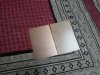
You just need a ic base and know the right pin configuration. The pin with the dot marking is pin 1, rest of the pins counting counterclockwise. Resistor values can be clarified from diyaudio forum or head fi.

I bought 10 pc of Resistors in each value and now they're mixed up.
I've tried using an android app to check their values with color coding but I feel it isn't foolproof, will a multimeter help ?

")
BB ROY GB VGW
Black brown Red Orange Yellow Green Blue Violet Grey White
0123456789
Mnemonic: BB ROY Great Britain Very Good Wife
PCB I have is similar to this hope it'll suffice.
I've been looking at all this stuff since day before yesterday don't really know where to start or should I start at all
:Many thanks for your kind gesture...I'd really appreciate if you can ship it thru...will happily pay for shipping and any extras.
Please let me if its possible so I can send you my details.
Sent from Samsung Galaxy Note II GT-N7100


It is nice to see some of the better-than-pro stuff built by our expert DIYers, but seeing someone taking first steps is also great. Might be an inspiration for some us to do the same, one day, instead of just looking at the massive power amps in beautiful cases, drooling, and thinking, "But I could never..."
Thanks for posting your continuing adventure!
You can cut open a LAN cable to get solid core copper wire too.
One of the forum members had used the vero board beautifully for his circuits. He used the small pieces of wire cut from the ends of resistors or capacitors or simply bending them. You can cut open a LAN cable to get solid core copper wire too.
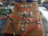
I'm getting correct reading when connecting ground to v+ and v- which is 4.4 volts in positive and 4.4 volts in negative...but when I add jumpers to connect the amp's v+ and v- to that of board I get incorrect readings...the amp am using is lm386
Please ignore the upper half of the board as its a failed attempt.
Sent from Samsung Galaxy Note II GT-N7100
I'll have to that eventually...but isnt it true that all 8 pin amps will have different pin configuration which can be had from their data sheet?
Sent from Samsung Galaxy Note II GT-N7100