DIY: Pass F5 turbo v2 initiated

Hi Friends,

Any one has F5 V2 PCBs? I am interested to build a Class A Amp.

Can any one suggest 3 way Loudspeaker design for this Amp? I like Bass extension at Low volume .

Kindly Help.
 
Friends desperately looking for JFET's 2SK170, 2SJ74 to complete the F5 turbo, burned the existing one while biasing


Sent from my iPhone using Tapatalk Pro
 
Updating the thread after a long while. Due to lack of time, I've passed on the kit to a FM w?h?o? ?t?h?o?u?g?h? an electronics guy, i?s? ?a?t?t?e?m?p?t?i?n?g? ?D?I?Y? ?f?o?r? ?t?h?e? ?f?i?r?s?t? ?t?i?m?e?. Best of luck to him.

Thanks, Capt. though this is certainly not my first DIY!!

Edit:
Moderator's note:
A new build thread has been created here: Pass F5 Turbo V2; one more build.
 
Last edited by a moderator:
Given some thoughts over placement of central part of amplifier.
  • This would have to handle large weight of two transformers.
  • There is some rectifier board + (optional)some softstart cum thermal cutoff board

image777.jpg


2 filter boards.

image779.jpg


I am thinking to have to layer approach to make it fitted into 12" X 12" space.

image775e.jpg


What do say if I build a frame of 1-2mm thin Iron 0.5"(W) angle to dimension 12"(W) X 12"(L) X 5"(H)?
This will allow me to -
  1. Attach heatsinks from sides, face and back plates along with top/bottom plates.
  2. Put welded partition which will support toroidal transformers as well as all boards too.
  3. Bear weight distribution and support the structure.
hi, I'm also building F5 Turbo v2 and I would like to make these pcb psu and rectification, can you help me, do you have diagrams or pdf ??? thank you
 
Re: DIY: Pass F5 turbo v2 boards update

Hi all,
Om has made final version for F5 turbo v2 boards.I am attaching images of each type of PCB.
F5 V2
3fullboardver3.png

By sachu888 at 2012-08-22

Power Supply Filter
psfilterver1.png

By sachu888 at 2012-08-22

Power Supply Rectifier
psrectifierver1.png

By sachu888 at 2012-08-22

We can start GB for above boards.One PCB set contains 2 X F5 V2 boards + 2 X Power supply filter boards and 1 X Power supply rectifier(Total 5 boards).All boards will be double sided,2 MM thick FR4 material,70um copper,Green Solder mask,with any lead free finish etc.One PCB set would cost you Rs 3000(approx) if 10 or more members are ready.
Jims Audio or any other F5 boards are 1.6 mm thick with copper finish of 35um(this is just for comparison).Let us know your views.

Regards,
Sachin
hi, the pictures are not seen, can you post? thank you
 
Hi Friends,

From a long time, it was in mind to have nice class A amplifier. Pass Amplifiers don't need my introduction. It's well known to DIY circles. I am churning out all available material on forums.

As subject states I am referring this - http://www.firstwatt.com/pdf/art_f5_turbo.pdf

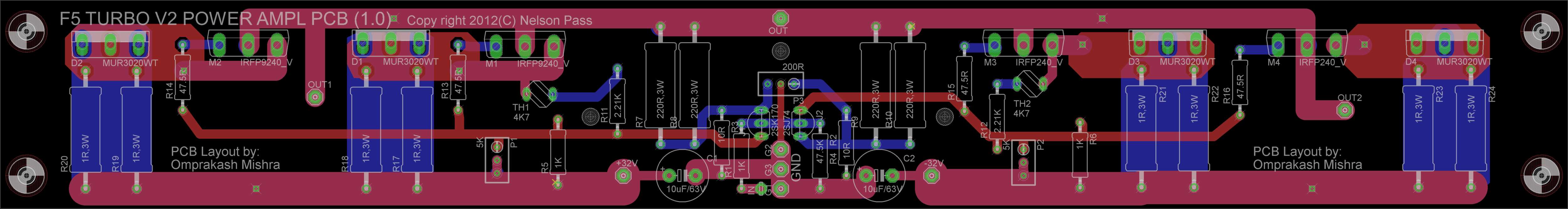
I went ahead buying PCB for my build. But unfortunately I find some issues as PCB tracks are thin as well as they are 305mm long, 5mm more than my heat sink. So I designed with following thought in mind.

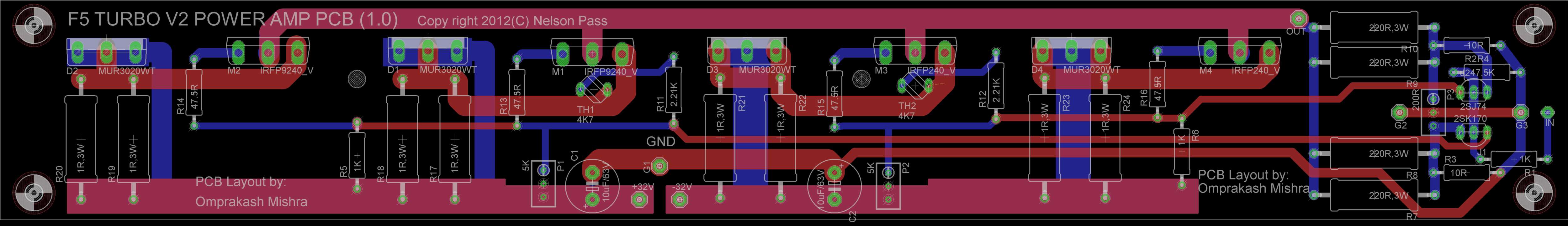
1. For power and output it is both sides will be overlapping. size will be approx 295mmX42mm (subject to change)
2. All heat producing devices are equally distributed at one edge.
3. using thick copper with wider tracks on both side.
4. Avoid in-out crossing to avoid oscillation, mind this is wide band amplifier.

These are my layout with two proposals -
Proposal 1: This will have input at center and will be same layout used for left and right channel.
1fullboardver1.png

By boundry at 2012-08-17

Proposal 2: This will have input at once end and left - right will have different symmetric PCB.
2fullboardver2.png

By boundry at 2012-08-17
Let's discuss pro's and con's of these two approaches. Further story will unfold as this project make progress. ;)

Thanks,
what are the sizes of the two proposal boards?
 
Join WhatsApp group to get HiFiMART.com Offers & Deals delivered to your smartphone!
Back
Top