keith_correa
Well-Known Member
Shhhhhhh!!!!!!which i discovered has the superb property of imitating an ordinary 12 awg lamp cord.


Shhhhhhh!!!!!!which i discovered has the superb property of imitating an ordinary 12 awg lamp cord.
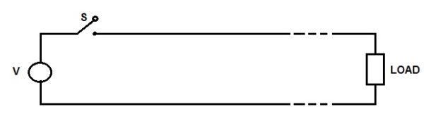
One has to be careful when making analogies. For example, I don't think that the analogy involving water build up holds water. That's because if the transmission line is either infinite or terminated in its characteristic the input impedance of the line is purely real (resistive). If so, when the switch is closed, there is no buildup, and the current that flows into the transmission line follows the applied voltage instantaneously.Here now with some math. Went back to revise travelling wave theory that we did in final year EE 33 years ago. got a similar explanation on the net
Velocity of travelling wave in a line does not depend on frequency, simply on L and C of the line. And for a lossless line 3 x 10^8 m/sec or 300,000 km / sec and it may drop a % or so with real world lines. We have hardly a couple of meter to discuss.
Travelling Wave on Transmission Line - Definition, Characteristics and Velocity Calculation - Electrical Concepts
Travelling wave on transmission line is the voltage / current waves which propagate from the source end to the load end during the transient condition. These waves travel along the line with the velocity equal to velocity of light if line losses are neglected.electricalbaba.com
What are the measurements that have been made that demonstrate the "improved high frequency capability" that you claim, and where have the results of those measurements been published?The wire that is subject to discussion in this thread, is certainly not just any Mil Spec wire !!
It is specifically.............. m22759/11.
The /11 designation refers to wire where individual copper strands are each individually silver plated.
The /11's silver content is important, since the silver allows for an improved high frequency capability. over bare copper.
Jeff
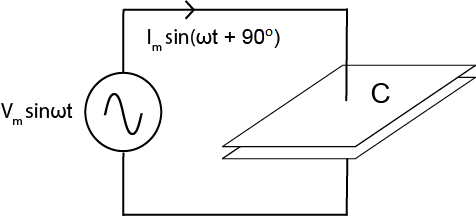
Was trying to recollect my memory..does not the frequency affect the capacitance and the inductance ? hence the velocity may not get affected but different frequencies see different impedencesHere now with some math. Went back to revise travelling wave theory that we did in final year EE 33 years ago. got a similar explanation on the net
Velocity of travelling wave in a line does not depend on frequency, simply on L and C of the line. And for a lossless line 3 x 10^8 m/sec or 300,000 km / sec and it may drop a % or so with real world lines. We have hardly a couple of meter to discuss.
Travelling Wave on Transmission Line - Definition, Characteristics and Velocity Calculation - Electrical Concepts
Travelling wave on transmission line is the voltage / current waves which propagate from the source end to the load end during the transient condition. These waves travel along the line with the velocity equal to velocity of light if line losses are neglected.electricalbaba.com
One has to be careful when making analogies. For example, I don't think that the analogy involving water build up holds water. That's because if the transmission line is either infinite or terminated in its characteristic the input impedance of the line is purely real (resistive). If so, when the switch is closed, there is no buildup, and the current that flows into the transmission line follows the applied voltage instantaneously.
yes. Impedance due to capacitance and inductance are frequency dependent.Was trying to recollect my memory..does not the frequency affect the capacitance and the inductance ? hence the velocity may not get affected but different frequencies see different impedences
Was just thinking if the above works then its possible that the harmonics of the same fundamental being at different frequencies would be attenuated differently and hence the tonality of the sound changes ?

1. Certain class of people will say. Wow!! This cable is so good. This has got good bass.
2. Certain class of people will say, Shit!!! This cable is so bad. It has lost some high end, some sheen from the music.
Inductance causes impedance to increase as frequency increases. It is directly proportional to the frequency and the inductance. Any twist and turns of cable will cause inductance. But in general inductance can be kept quite low.
View attachment 69640
Consider the cable impedance and the preamplifier impedance to be in parallel. For argument's sake let's say the preamp has an input impdenace of 100 kilo ohms. At low frequency the cable impedance is very high at few mega ohms. At high frequencies, Let's say 15 kHz, it becomes around 100 killo ohms. For 400 Hz, it is 4 mega ohms. So if you have the music source fed to this preamp, high frequency of 15 kHz will see a impedance of 50 kilo ohms. But 400 Hz and below will hardly see any drop in impedance. This will hardly attenuate the low frequency component, but will attenuate the higher frequency more.Thanks , very nicely explained. I do have a further clarification/doubt.
Suppose we take a simple sound like the thump of a Drum ( just one beat) at say 80Hz.
- its going to have Even Sub harmonics at 40 Hz and 20 Hz and a tactile signal at 10 Hz. Odd Sub harmonics at 26.67..etc
-Its going to have Even Harmonics at 160, 320 and odd at 240 and 400 etc
The Timbre of the Drum is a complex wave, which is a summation of all the upper and lower harmonics which create the sound envelope for that beat
I assume all of these signals are sent out from the Amp to the speaker and will suffer different impedances ( Cable + Speaker loads) since frequencies are different and hence the capacitance and inductance are different ?
I am wondering if at some level the there will be some losses which will vary by frequency and hence the Timbre will be slightly different when reproduced in comparison with another cable which may attenuate it differently due to its L&C being different ? ( the difference can be insignificant though)
correctI have a question, and request your help..
You say "Any two conductors close to each other causes capacitance. " This is how I have always understood it . Increased capacitance kills the highs. Twisting polarities, increases capacitance, kills the highs.
If you don't twist the conductors, you will severely impact the noise rejection capability of the wires. The computer is full of noise producing equipment. The capacitance has been brought to very very low levels due to excellent work done with Chemistry by the scientists in ensuring that the electrons in the insulating material doesn't move when electrical field is applied. So by twisting you will sure increase the capacitance but that is much of a lesser problem because it is already very low. Just consider that between the two evils in computer transmission, noise is the bigger evil than capacitance (which is already low thanks to thin copper wires and good dielectric).Then you go on to say .......
" The twisted pairs inside CAT cables have the copper wires coated with a material with a dielectric that gives very very bad capacitance. Hence it is very good for high frequencies. "
correct
If you don't twist the conductors, you will severely impact the noise rejection capability of the wires. The computer is full of noise producing equipment. The capacitance has been brought to very very low levels due to excellent work done with Chemistry by the scientists in ensuring that the electrons in the insulating material doesn't move when electrical field is applied. So by twisting you will sure increase the capacitance but that is much of a lesser problem because it is already very low. Just consider that between the two evils in computer transmission, noise is the bigger evil than capacitance (which is already low thanks to thin copper wires and good dielectric).

Thanks , very nicely explained. I do have a further clarification/doubt.
Suppose we take a simple sound like the thump of a Drum ( just one beat) at say 80Hz.
- its going to have Even Sub harmonics at 40 Hz and 20 Hz and a tactile signal at 10 Hz. Odd Sub harmonics at 26.67..etc
-Its going to have Even Harmonics at 160, 320 and odd at 240 and 400 etc
The Timbre of the Drum is a complex wave, which is a summation of all the upper and lower harmonics which create the sound envelope for that beat
I assume all of these signals are sent out from the Amp to the speaker and will suffer different impedances ( Cable + Speaker loads) since frequencies are different and hence the capacitance and inductance are different ?
I am wondering if at some level the there will be some losses which will vary by frequency and hence the Timbre will be slightly different when reproduced in comparison with another cable which may attenuate it differently due to its L&C being different ? ( the difference can be insignificant though)
The impedance and resistance determine the attenuation vs frequency. This parameter is normally expressed in dB/1000 ft at a given frequency. This is a measure of the amount of signal loss that occurs from the cable. More signal is lost at higher frequencies than at low frequencies. Remember that the rise time of the pulse, not the data rate, determines the frequency range covered by the signal. Since there is more attenuation at higher frequencies than at lower frequencies, signal pulses are dispersed as they travel down the cable. This property is measured as rise time degradation. Rise time degradation is roughly proportional to cable length. System designers are constantly balancing rise time effects. On one hand, fast rise times produce more crosstalk, that will, if great enough, result in errors. On the other hand, slow rise times that get further degraded will cause receiver errors. Lowering capacitance improves the performance of cables used for both unbalanced and balanced transmission....
I guess if you don't have any noise, emi pickup by untwisting the wires, it will definitely be better than having them twisted as far as frequency response is concerned.OK. Thanks.
I was really only thinking about audio wiring and audio design. In the last several years, I have been untwisting wires, and splitting dual channel molded interconnect cables so as to have separated wires, and it consistently translates into subjective listening improvements with my home's equipment.
In my experience, twisted cables are more beneficial sonically and also in terms of layout. I have been in situations where straight wires have also worked with no sonic advantageos, but where EMI/RFI is prevelent, twisted is the way to go.I was really only thinking about audio wiring and audio design. In the last several years, I have been untwisting wires, and splitting dual channel molded interconnect cables so as to have separated wires, and it consistently translates into subjective listening improvements with my home's equipment.