goldyrathore
Active Member
I did a lot of trials with not so good results initially. I had almost given up with these drivers. After incremental tweaking, finally managed to get some good results.
Here is the 2" plot. As you can see there is pretty good response from 500hz to over 1k.

And here is the Sony 2.5" plot. This one goes from 200 hz to about 1k.

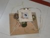
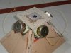
As mentioned earlier these results are after sealing the rear chambers. Considering that I ve not used any simulation so far (for the mids) and only relied on my bandpass sub experience from past, I think these are very nice results. The setup is temporary so not posting the images.
This gets me closer to tap the horn:clapping:
Goldy
Here is the 2" plot. As you can see there is pretty good response from 500hz to over 1k.

And here is the Sony 2.5" plot. This one goes from 200 hz to about 1k.

As mentioned earlier these results are after sealing the rear chambers. Considering that I ve not used any simulation so far (for the mids) and only relied on my bandpass sub experience from past, I think these are very nice results. The setup is temporary so not posting the images.
This gets me closer to tap the horn:clapping:
Goldy


")