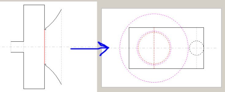
It's just a way to capture the lowest freq air column resonances (the ones hardest to damp) instead of treating the volume only as a pure compliance. Parallel walls => standing waves. Straight pipe closed at both ends = half wave resonator, but with two holes in it (driver & port).
Maybe look at the open cylinder harmonics three things down
here and just mentally shift the waves 90 degrees to put the nodes and antinodes in the right spot for a both-ends-closed pipe
")
Modeling this way is the attempt to capture that and get it in the impedance and the tuning and the response, etc. As-conceived, the reality will measure lower-tuned than the vcad 5 parameter reflex model--HR tuning modeled the height way will be closer. You can then stick some filling swag in there, see what it does, and export that impedance to use--not as good as reality, but better than simple reflex model unless the real box doesn't have that cross-batt, etc.
If the real port was in the middle of the back, then the way you had it would be a better model (assuming cross-batt still used or non-parallel top/bot). How you model depends on what you want to see (and what you *know* is happening), right?
Again, at this point, the boxes are done and it's all much ado about nothing except for reference/posterity, but this is why to model that way. Where you put the driver can null-out a harmonic. Where you put the port can go after a higher-frequency, etc. The cross-section is the plan area of the "triangle"(ish) main body of the air column. This stuff is a continuum/gray with regard to the distribution of harmonics. The details matter once extra shapes or chambers are involved--and it's almost never well-behaved. Tapering changes things as well. End-driven, end-tapped, tall + skinny is the worst/hardest. Squatty is feature when things get big
When height and driver & port offsets are chosen, you are freezing-in the distribution of the harmonics richocheting around inside your cabinet. The only tools left are lossy (or more acoustic filtering chamber games).
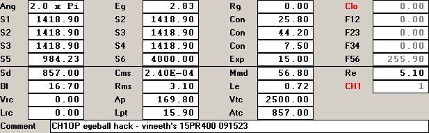
Adding on a fronthorn length and throat chamber length goes into the resonant circus, too, but here you sidestepped some ugly MR ringing by using the big throat (St > Sd). I didn't see that yesterday and just blindly assumed that all the wood gnawed-out was for a conical front chamber volume to lowpass everything acoustically--figured you guys already hashed that out and did it to eat HF from the woofer, etc. Strictly-speaking, I also messed-up the throat chamber which, in this specific model, should have been put in the RC entry as Vrc 2.5 and Lrc 2.92 with Vtc=Atc=0 so it went in the right place, but the big throat mostly negated the mistake.
Pragmatically, every tradeoff in a big 2-way is a painfully difficult choice and here the driver must be high and things are what they are and all will be fine. The symmetrical fronthorn offsets the driver down a ways to its own benefit. If this were all a brand new blank sheet design, you could iterate various port and driver locations, etc.
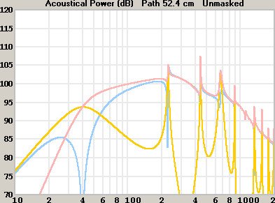
The main column resonance is an extra "load" (or free damping if you prefer) when boxes get toward that size. All reflex boxes are a combination of the "normal" (simple) LC (inertance-compliance) resonance and the air column size resonances--it's just that most boxes are smaller so either the harmonics don't get excited as hard (ie are out of passband) or are more easily dampable (higher freq). In big boxes, these resonances can muck-up the low-mids (response squiggle 2XX-6XX). The cross-batt of fiberglass between driver and port will aid cleaning that up.
As in all matters of audio, you will see opinions advocating everything from the empty pure compliance to the nearly-filled TL-type. Acoustically resistive treatments are a wonderland for experimentation that, once-heard, become as personal as food preferences IMO. Critical damping is a fine goal but most people also like a little ringing/ripple to "fill-out" the sound of soundbodies.
The old ways of blind empiricism still work, too. Battery (1.5V) + momentary switch (woofer only!). Add layers of fabric over ports and repeat make/break. Listen both directions and add fabric until it clicks and doesn't "bong". Stapling fabric over the rear of the driver damps both the driver and the cab instead of just the port. Loading the port with straws, etc for some more friction, etc. Hanging curtains away from cab walls. All these things are tools. The filling/lining/damping is personal, it's box-specific, and it depends on what's driving it, too (source resistance).
Some acoustically-resistive things are simmable, but it gets back to needing to measure to verify the sims before they're trustable anyway. To add more detail, well, HR is out and other tools are required (each with their own issues).
I really only meant to show the standing wave influence, slap a hunk of filling in the middle and show all that trash getting knocked-down
It'll be fine. If it's empty (unfilled), should have a couple squiggles 2XX,4XX,6XX Hz, should show in the impedance, too (empty). Congrats on the big boxes and well done. Wish I could hear 'em. Putting them in a corner will help lift the bottom to catch-up to the fronthorn some but maybe you have subs for low-lows, etc and don't need it or were going to tune higher, etc. At any rate, outstanding project and thanks for posting.


 . The attention to detail and workman ship have been top notch. I must say, there was a lot of love poured into this one
  .
. . Very happy to have someone with your knowledge and experience, and a willingness to share


