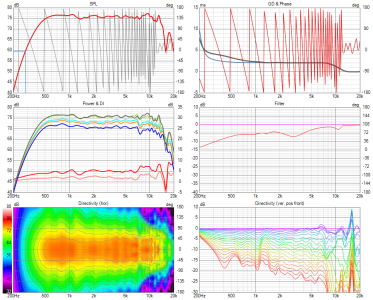
2-way horn system based on the mk3b2

If so then did you consider making it an MTM with 2 x 15s? Pretty standard to improve sensitivity and output. A folded horn is not usable upto 650Hz so it is a moot point. If you are very good you can design one that will measure that far but it won't sound good. A straight horn, now that's something else but to reach 40Hz the length/depth would be prohibitive in most user cases. I have heard a lot and I can tell you with certainty, at least for myself, nothing sounds like a straight horn and nothing can beat it. A no limits system will always use a straight horn in my book, whether open/ported rear or sealed or some other type might be debatable.
Being cautious, mostly, with size and expenses. I can always add another bin on top to make it an MTM in the future. Since the woofer bins are not attached to the horn I can always add the bin from the second speaker atop the first one to get a "feel" for it.

Interesting, good to know. Do you actually build all your projects yourself? Without carpenters?
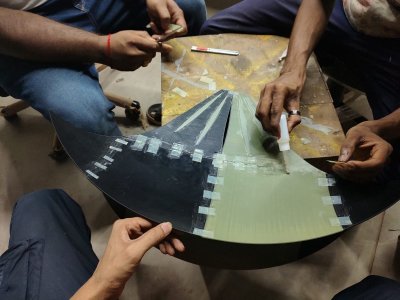
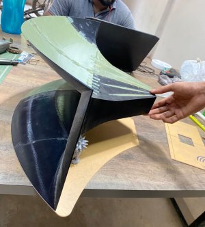
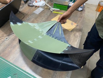
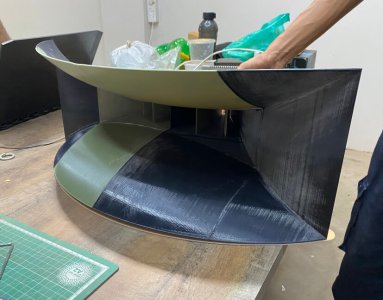
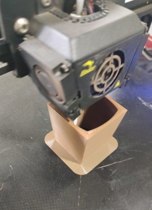
Yes to the woodwork. The 3d printing has been outsourced.

I also am curious why you do not wish to build a folded horn? By this I am assuming you are including a straight horn also.
There is no "technical" reason why I wouldn't try it. Just don't "feel" like it atm.
 
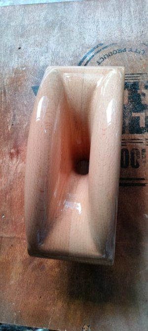
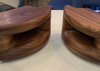
Mine is solid wood and weigh 16kg each and took very long to make…
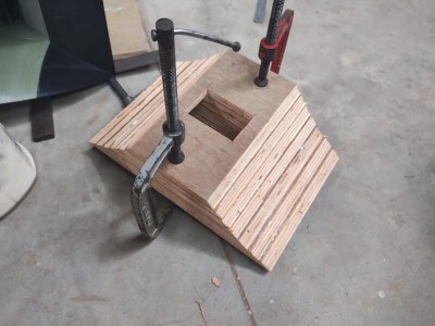
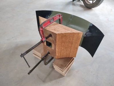
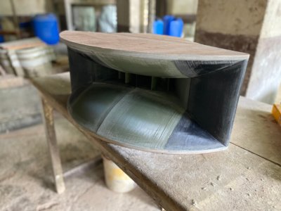
The second horn will be made of wood, as this turned out to be a pain to align the sections for glueing. This was a great learning experience, we are tweaking the build process going further. Do you have a picture of your horn? please share.
 
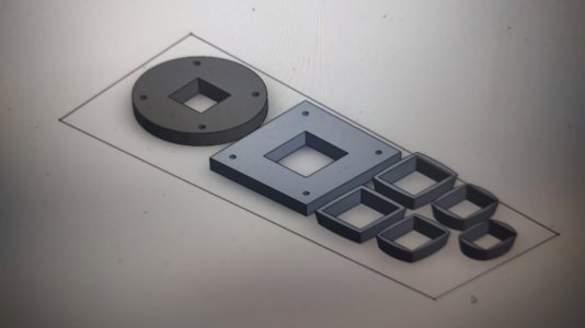
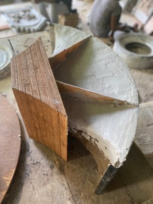
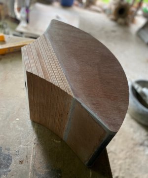
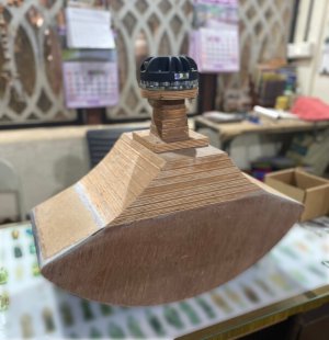
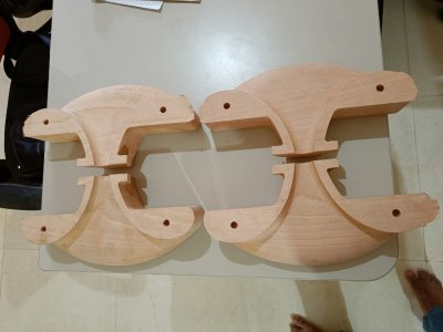
Vineeth has been kind enough to provide the dimensions for the adaptor. This is the inner piece which will then be clad in plywood, including the flanges at both ends.

76497d67-ac48-4e3a-a02e-67b8918800c1.jpg


These are the wooden sections that'll cover the throat of the adaptor. CNC work.

24d6807b-c107-48d5-90e6-e7fe65fb4bb8.jpg


Great Job. Very Nice to see the project taking its shape. Your dedication can be seen in your work..... Excellent.
 
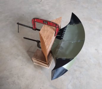
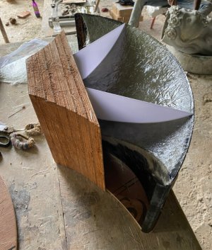
Ideally, I would've liked to have a rubberfelt insulation layer between the fibreglass and POP, but alas, I was unsuccessful at procuring it.

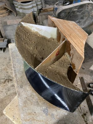
Coarse Sand dabbed over and stuck to a layer of thick resin paste, to ensure that POP adheres.

IMG_3144.jpeg


Applying a 1.5" layer of POP mixed with PVA glue.
IMG_3146.jpeg

IMG_3147.jpeg

IMG_3159.jpeg

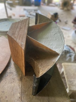
The inner surface will be sanded down to a smoother finish.

IMG_3157.jpeg


The prototype is ready for testing.

IMG_3162.jpeg
 
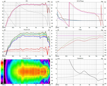
So we did extensive measurements of the horn with the Faital pro HF146 compression driver.
A lot of hardwork went into getting these measurements.
Just Hats off to @aeroash for doing a hell lot of hardwork for this on a sunday :)

So here are the measurements. Enjoy.. :D
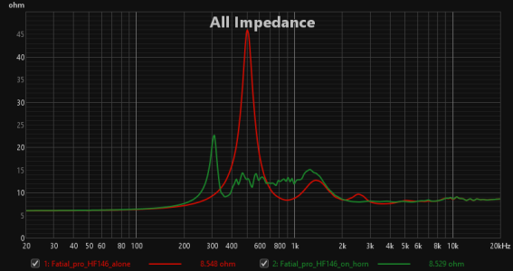
Impedance measurements of the driver without and with the horn
1688635892290.png

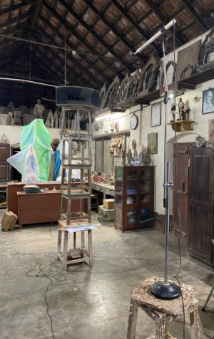
Here is the measurement set up for horizontal polars (Mic 2m away from horn)
1688635805036.png

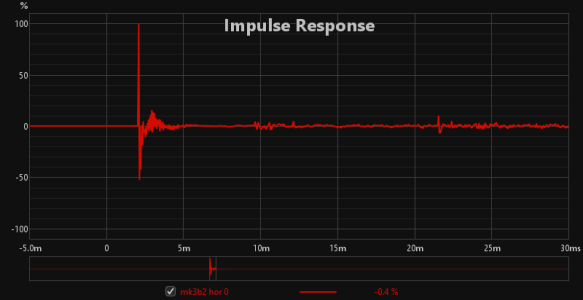
Cleanness of impulse response for on-axis measurement
1688635831202.png

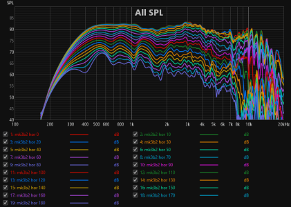
Raw measurements (0 degrees to 180 degrees off axis) gated at 6ms
1688635856721.png

Spinorma data with frequency response flattening equalization applied.
1688635970753.png
1688635964521.png

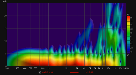
Energy decay
1688635999331.png

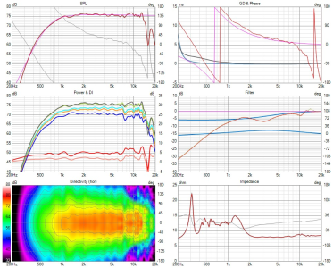
Applying a Linkwitz-Riley 4th order high pass filter showing a potential high pass that would be applied to the CD+horn in a 2 way system

Active version
1688636101654.png
1688636111812.png

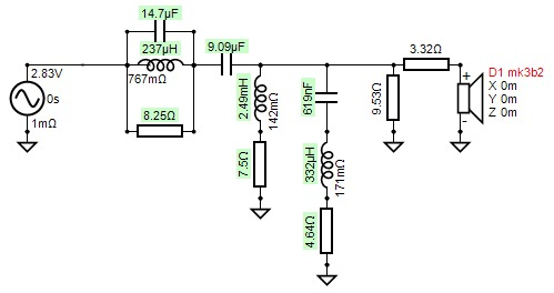
Passive version (not the optimized one and just made using transfer function replication based on active system crossover above)
1688636154515.png
1688636164641.png

Way forward from here
This is a really good constant directivity horn it seems.
To get the last drop of performance (including high frequency extension beyond 14kHz) from it and to explore more possibilites, we are doing more testing. Testing with other drivers and other more optimized/sophisticated driver to horn adaptors to follow.. :)
 
So just a clarification about this horn.
This is not the standard Yuichi A-290 horn in the strict sense.
The fin geometry & horn profile has been modified in the mk3b2 design which we are building here. The original Yuichi had some issues especially in the polars (including midrange narrowing), which are supposedly got rid of in this design.
@yogibear: Is your horn the A-290?
Also, could you let us know what drivers you plan to use with your horn?
 
So we did extensive measurements of the horn with the Faital pro HF146 compression driver.
A lot of hardwork went into getting these measurements.
Just Hats off to @aeroash for doing a hell lot of hardwork for this on a sunday :)

So here are the measurements. Enjoy.. :D
Impedance measurements of the driver without and with the horn
View attachment 78188

Here is the measurement set up for horizontal polars (Mic 2m away from horn)
View attachment 78185

Cleanness of impulse response for on-axis measurement
View attachment 78186

Raw measurements (0 degrees to 180 degrees off axis) gated at 6ms
View attachment 78187

Spinorma data with frequency response flattening equalization applied.
View attachment 78190
View attachment 78189

Energy decay
View attachment 78191

Applying a Linkwitz-Riley 4th order high pass filter showing a potential high pass that would be applied to the CD+horn in a 2 way system

Active version
View attachment 78192
View attachment 78193

Passive version (not the optimized one and just made using transfer function replication based on active system crossover above)
View attachment 78194
View attachment 78195

Way forward from here
This is a really good constant directivity horn it seems.
To get the last drop of performance (including high frequency extension beyond 14kHz) from it and to explore more possibilites, we are doing more testing. Testing with other drivers and other more optimized/sophisticated driver to horn adaptors to follow.. :)
Nice. The resonance around 14khz could vanish after some break-in. Do not modify anything now, try playing some white or pink noise at moderate level for a couple of days and measure again. It will be interesting to see that.
 
CNC machined.
 

Attachments

  • D23D59CC-1734-4A0A-8755-E2006506FC9F.jpeg
    D23D59CC-1734-4A0A-8755-E2006506FC9F.jpeg
    88.9 KB · Views: 29
  • 8CDB3653-C665-44A4-A4BC-95772FB14C77.jpeg
    8CDB3653-C665-44A4-A4BC-95772FB14C77.jpeg
    104.2 KB · Views: 28
I am not an expert in Speakers. Just supporting diy to realise idea.
I don't think anyone is an expert here. Me included. The question about horn cutoff frequency is a basic one which even a novice will ask imo. Since you are having the horn with you - it could be measured or calculated.
 
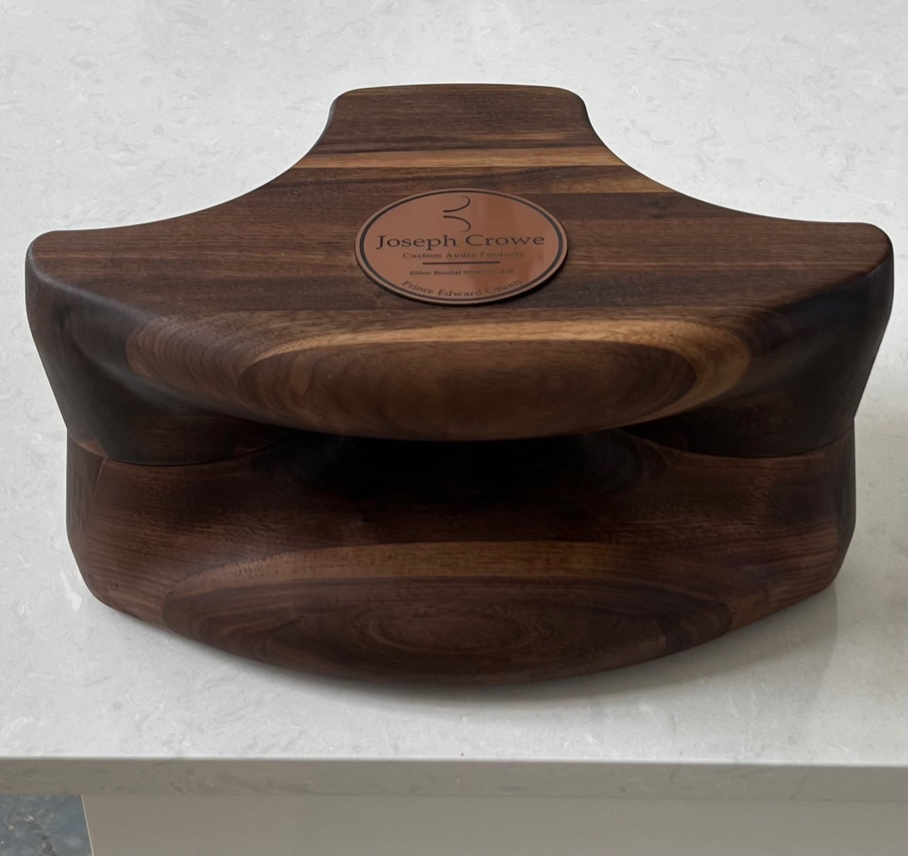
I think it is one of the ES series horns by Joseph Crowe listed here:
The particular horn shown above could be this:
 
I don't think anyone is an expert here. Me included. The question about horn cutoff frequency is a basic one which even a novice will ask imo. Since you are having the horn with you - it could be measured or calculated.
I guess you didnt get my earlier reply. I am just facilitating manufacturing of these horns. Which is my expertise.
 
I guess you didnt get my earlier reply. I am just facilitating manufacturing of these horns. Which is my expertise.
Great. Can you help me build one pair. Currently in my OB I am using a Dayton Audio waveguide. As this is plastic - I want to change them either with a metal or wooden horn. Do let me know. Thanks.
 
Follow HiFiMART on Instagram for offers, deals and FREE giveaways!
Back
Top