Kuartlotron Error Correcting Super Buffer

hi friends,
i'm facing an issue from my K Buffer: while playing music, the volume suddenly dies down and i can only hear feeble sound of music. this was even before i could finalize the chassis etc. after testing for various voltage measurements as specified on preamp board i found that the input voltage of 0,-10 was fine but 10,0 was dead very low was reading something of the order of 0.2 volts.

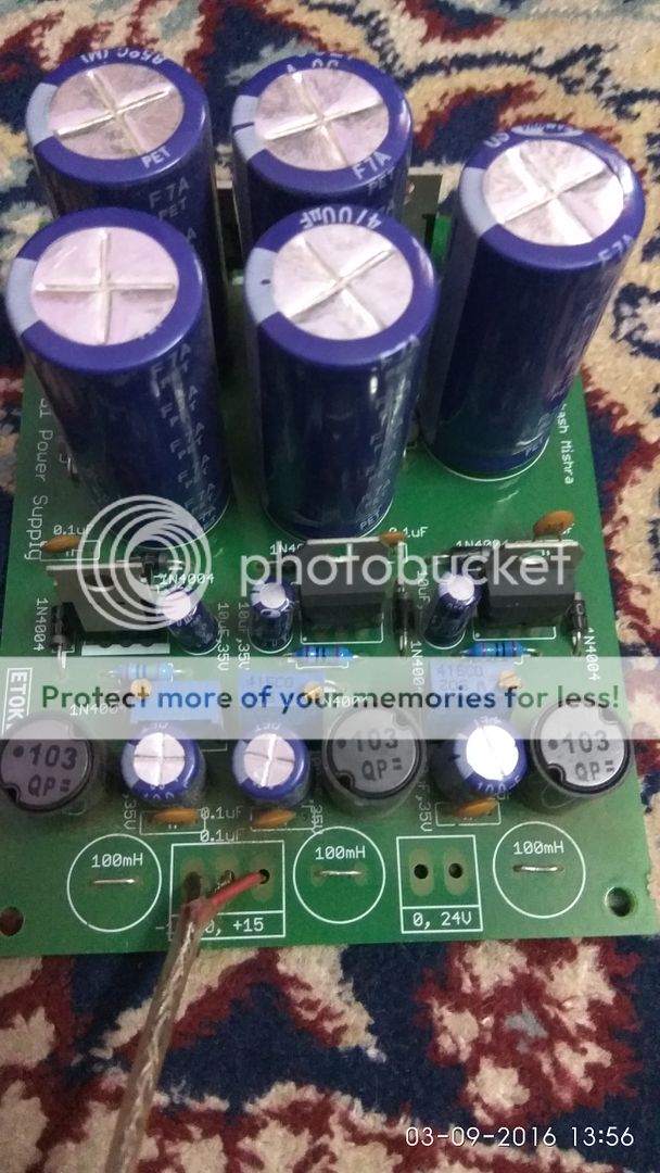
later i traced the issue to one of the 3 trimpots [middle one in the pic] responsible for voltage tuning. if i touch the trimpot it would play just fine [voltages restore] and also i noticed that the trimpot had 5K OHM irrespective of turning the screw. i replaced the trimpot with new one. it had been playing fine for more than a month. but the same issue has reoccurred. this time around i'm planning to replace the trimpot with a resistor [trimpot now measures 2.2K OHMS]. but while playing if i try to measure the resistance on other 2 trimpots on the PSU PCB , my multimeter shows infinite resistance. perplexed, what could be the exact issue?

20603d1459722634-kuartlotron-error-correcting-super-buffer-a4img_20160404_032241.jpg
 
Last edited:
Show the downside picture of PCB around same blue preset. It looks like lifted PCB track or solder pad to me. Please check there.
 
I had a lifted PCB track problem below a Bourns trimpot on one of my OPS boards. I simply shorted that trace with a wire.
 
here are the pics,
@omishra
soldering looks messy after desoldering the trimpot first time - it was a PITA. issue is with the central trimpot .

@jls01, are you referring to left 2 leads of trimpot?
-29VKZkXbG8kDnTDkElH-pzmp1_L-l7fO9LtsDvZRCWM1RTPvNgZOcYBwH5R0v3Ne7O2IIDmAaUogTjmF2DgkTUTSfE0-LuESqat-tQIGXBs_XRjFcqktYcBE1Q0mQvi2FO9qA-tWViqK4MBDgu8qs9Hj_emngqJ8aVkfXCeD6A8Mmb3XGSjewNN8VnE3L9X_rkt-mO_nOibRKJiJjuSm-L48wOJRyOojPqUy2frkTWBnKzElT1DoKtoqKpw7YEH_UYWOINTwgntBa__5hvwknNRew7p1Sr0rt85MkC2f8oDMyNwmena0kqHWyYhljkcK068rJmV8wDlMHd9tOPvfKSLesqAFLA5ul38xSX9RBK7_JYFNRnMyQ7O7c_mZeIZPY9tTtjMYwVT64h_zZjVvrO4GX851qmMU2WI5oT5riT4Mx3NDd3889GMd-2f9gMFgaFbeprUCMZJNcaUm4eyP9ye_uPc_UGmU36G1-v1kaZbMUf9ZsUC1L8-hJbMz0kUgLTKER35IwG9x6wxsQz92BkwtJiWcFHjXy_2UUyp-TkKIxUHEy3gP7AoqU57zAJ4mKNp5lKPswvwYmIiwrGNl9A8FeI-QUE7XnLbzU2VK0mNtuir=w1187-h837-no


@Sachin, there are no jumpers on the PSU board
Q4IaUTDkDV03s3mb_7ePUVN-3JtEF9I3mEBHUYvs39qeK5MFgYo1dlgKG60nfW1qwP6zOdhCD1sLXcIQyMII_zu54sKTCX-XrNr16xmUgjlCtRAmAsHQoEg7Vhml_i4-JQS1gyypdwU6vYrlV4Vz0joGx9Aw_RjjYHyPxLRlfdk-zBj2gYmRoAFiPAIZ8lRHydIz5S1yz6Fb2_ZAyTK9SJUFkcnR_KY1hUq_d9NtYt36Zb8E-enwZoOoi--q_DRg92Y0WCNM_sQTKOH_uSXwiWqGePYJLbQzADdsG-N_9I6BOc2-jLFm59PdhJrqqBzIJIRB_tAQr3Bqc7WqyIUA5YbBJyxHb5Ve2DbULE8l3DT6l9llL6eupnEmnLBMxIeADXW_B6S4t_JIIPDycjANORtg_xit7O_0zrw9VTn0Q7VmNQq_jzXbaXvgIrpmydoAatRjLhfZxiSP_lU05meWRMn79ZZ6MSqHBDuXHFvJVHdCSrQlhJ5iXwvSaoFWEMnbTfDKBGLMSCNpaldJhl9R2fxWbY2zqNppLnK2vUOwIzzDJRn1MeSgrqM7KUf3pzX3MWtWNEpJb89u-RtzIzATySPQYnT8cDv3pLKvPpDlNF6cYng8=w1561-h837-no


PS: not sure if pics would show up, i've been facing issue in sharing pics
 
Last edited:
The middle lead of the trimpot is shorted to one outer lead in the PCB itself. Correctly installing the trimpot decides whether the trimpot value goes up when screw is turned clockwise. If wrongly inserted the value increases when screw is turned counter clockwise. Electrically they're equivalent and both will work but it's a good practice to mount it correctly so that clockwise turn produces increase. I think it was this shorting trace that came off and gave intermittent problems like you're facing.

Use desolder suction gun from Soldron (it's cheap and works well) to cleanly desolder the three leads, remove trimpot completely, use suction gun some more to clean up the pin holes, then insert trimpot and apply fresh solder. If possible, use fresh trimpot of same rating. Minimum quantity of solder is enough for good contact.
 
its probably a good idea to redo all the joints, apply some flux and heat all of them. see some other builds to see what a good solder joint should look like.
 
@Sachin , never thought about jumpers as it wasn't available in the kit
@doors666 yeah, i need to improve on soldering : as jls001 mentioned i'll get a suction gun.
but is it possible that trimpot gets damaged because of any previous component in the chain? also now that i know what should be value on trimpot isn't using a fixed value resistor a better option? how susceptible are trimpots to heat damage caused by overheating by solder gun [are they more sensitive than other components]?
 
Jumper is nothing but small copper wire leftover after cutting any components leg. Just solder it over white line J1 parallel to 22-0-22 marked box.
Trimpots doesn't get damaged. Use it, otherwise it's 5K bourns preset. Fixed value is difficult to calculate due to component tolerances. It would mismatch with other rail by few mV after putting fixed resistance.

oops! got confused jumpers with wire terminals! i've used the jumper, it's not clear in the pics!

EG4TgG2xMyp5gOnfT5ZJRiGpB2T1oLWntiQUCaj1D9xyqNbJfXo53jcLzjtZG7PBOD82uMlv-mR101BEi2WJOPYdFNUfOxiDOa2lkine21qlj4BQ1KfrsC5djUw35zKhsqN_1plo3SW2_cE0qAKxMih7i3lIKJzva5j4-AGIAKs1WkTdG__6_76W7m8fNffbedBtVjzVlW_p37DvvUe8zyPYOkP6hVlzKyibpJOLHbInLuJr7-St2p9EqKuG873ZYp3644HJbkBJNUbNWkkR5RAaFLRYzyG3W5KJDkxgQ9mAlrUPiH4jhvjhbA2ZFYYWqkZJ5iBYG7_jdNq527MtPhpsns_zVacKjYi3yQ2b9zALIy4cOOaxI1JTLa3gm88kHmIw1bxmoS2l6SfAuFVJDhyZPyOwHFC_nA3vcs9hr-SWPZEMnHsVYmuVI1O8FYEOjcWaIrqmqH1MPj46efc9TASbYs7Xs28beQFj-MnT-VgiLFYtf5767vng21RDrXvt5SbfYy2T80fRIgvgskpwS_U62DsxVf_Dd-9uV8oNKA_GI-L1VtGJm03kKfkYD8A-UCyhh_td4ONSE_8UHUnx4DGkHl865GY6iVjTBaW9pjkFQ1tI=w261-h335-no


as suggested by FMs, i'll start with desoldering the messy ones and solder the new 5k trimpot [i've few of them with me now!]. probably it'll server as some more practice for my next project!
 
Please make the PCB at least like below shown. Cut the excess component's leads with wire cutter and use IPA to clean the excess flux with IPA.

I have observed that if ceiling fan is at high speed it makes soldering less neater, it cools the led settle quicker which makes the soldering difficult.

IMG_20160903_135458_zpsdfckuhtz.jpg


IMG_20160903_135652_zpszj49hxq0.jpg


Regards
Bilal
 
While soldering I switch off fan and avoid direct air from window too. Cleaning with IPA is good idea. I too use it before and after soldering. Use of soldering flux and heating for 3-5 sec is enough.
 
Hi @sachu888 , It's only today I decided to populate the Kuartlotron buffer board with the components. The only issue is that I am left with two 56R resistors. In my kit I received 4 56R. Two have gone in the board R2 & R13. Where does the remaining 56R resistors go?

Also what is the procudure for setting the four trimmers?

XHcJW4wLzlxEjqhnzTBRJnToeV9ahQdnv5kNYF4SdJ21mbw96PB8C30IZkQ1r10yhX73jbinf1NGe6L3VSfjTbvFhN65mjkRtX2b3MFJvRRGiqubg-Zvs5rvVLH4YK3cCJ7Wc1a0hsYtAkTepJnH4FEvDtNFmBUMq4voXoP6P_Wbyi50lgf9gxUDo7a9qWorr5FKxmSnUPwyseUhCuHKiwBbg_4PMzLU7JA6hAjBDdn65ZZ_HQ7is2yGbToBSPEwa1BXD9p2c5PFLgeu7fjhO21OngliQ8Z7jM5f_gv2waTnhKBOrYgLF9GDsaru3rPKsH_pfddympaL5PL9njpWHRA-8vHlA-UeL1SBqtT5p2m5T_rBR3m7JmNX8272ffp6LBE9GnEw8-zsAb4oyXy-eI4XVE5CNJY17zfCqknNtQQ-Elx7fm6a4mwffYPySvkEZwiCKBzv0l0MZ2aQL1nORwRJk7ZckxBlXYOzmwZyHZO_9mMH-LG-1bdfi-h_hL04X13qErYgVADQQ0Oieb-x5AApuwYuFZow9QYorbldrTqdmuRj7kKaUXG1lIrcdFvt_B0gp3lds6AKvsv4G_wPsnOKH4m-PgnQpXC8OOLHm0xXAHPEfIvcMORaE98yeX7oPVf87plKnDwlLjshzj2H1FNYNH75lFQFSynyDBcaidwnPSSc0ke5O88=w959-h719-no
 
Last edited:
...

2) next, short the left and right inputs and adjust value of trimmer R5 so that the reading at test point TP is exactly half of input DC voltage.

@jls001 For point 2, the voltage is to be measured between ground and the TP? Right?
 
I finally soldered K-buffer after long time. I wanted to know if it is safe to use +/-12V.

For this, I tried using LTSPICE simulator. And it seems like there is no particular difference between 10V and 12V. Wanted to know if I can use this. Attaching the simulation file.

Among other problems, I am getting lot of hum. But I haven't exactly followed the instructions of grounding as yet.
 

Attachments

  • k-buffer.zip
    1.3 KB · Views: 4
Wharfedale Linton Heritage Speakers in Walnut finish at a Special Offer Price. BUY now before the price increase.
Back
Top