Kuartlotron Error Correcting Super Buffer

Thanks Joshua!! I am thinking of adding a stepper motor controlled by IR remote ( a module available cheap online), it uses 5v 1000mA.
Does the PSU got 2 or 3 outputs??

And also i need to know which will be appropriate transformer for this, I see people using 12-0-12v as well as 15-0-15v R-core.
 
Last edited:
@Arun, this PSU was designed for 22-0-22 secondary voltage. can be used with lower secondary voltages too. since this thread is about K buffer which needs 10V DC, people are using 12-0-12 secondaries[R Core trafos].
further, the DC output voltage can be tuned with the help of on-board variable resistors.

in total, PSU has 2 outputs,
1. 10-0-10 DC to be used for Buffer board,
2. the other conventional 0-13V DC
[voltages might vary based on trafo and adjustments]
 
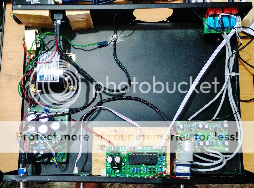
finally, finished mounting pcbs onto the chassis. there seems to be some loose soldering on PSU board. music stopped playing midway. after rechecking the connection it has been working fine.

-i've followed Joshua's advise of shielded cable use for signal path and the grounding one end to power ground [hope the connections are correct!]
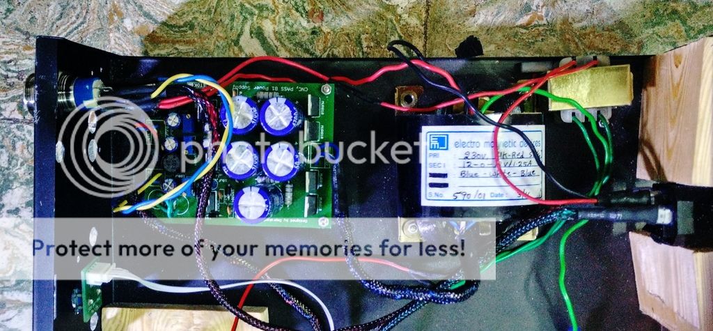
-i've tried to isolate the power circuitry from the signal wire/buffer pcb as much as possible
-i could adjust the second DC output on PSU to 3Volts: perfect for power button LED!

i know wiring is a mees, but this is the best i could do with the available time and patience!
the IR sensor and source input indicator board is raised on a wooden platform -right now held in place with 3M double sided tape.

IMG_20160414_043330_HDR.jpg


tiny trafo is for 9V AC input meant for Source Selector module:

IMG_20160414_042906_HDR.jpg


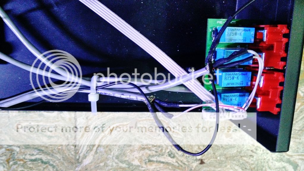
signal wires. though i had ordered Neutric RCA jacks for signal output, i found MX Connectors better built hence used them [not visible in pic].
also you can see the grounding cable [black]

IMG_20160414_042850_HDR.jpg


closer look of the grounding:

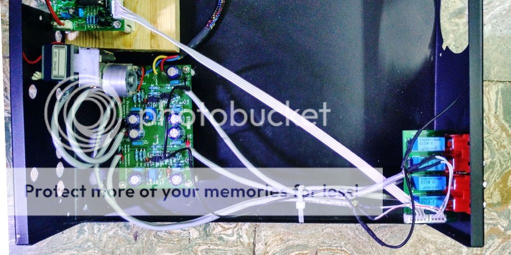
Buffer board as source,
IMG_20160414_043229_HDR.jpg


source selector as source,
IMG_20160414_043213_HDR.jpg


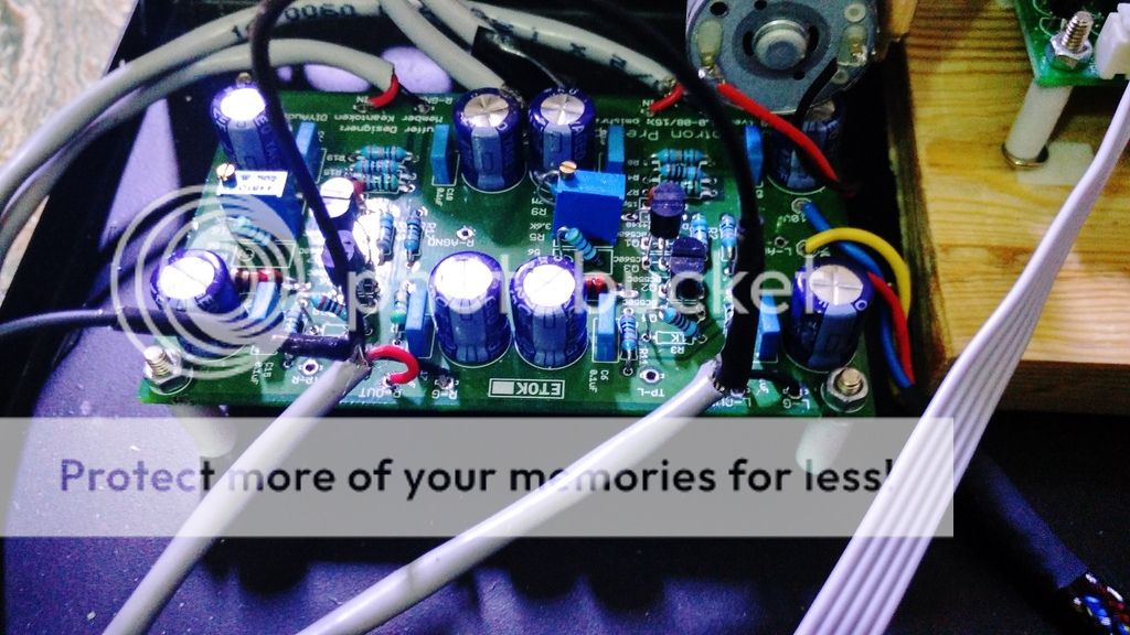
buffer board with ALPS pot connected using the shielded wire:
IMG_20160414_042837_HDR.jpg


preamp is yet to get a fascia - cosmetically it looks crude.
 
Last edited:
It looks fantastic. Looks like all preamp features packed into one box. [emoji4]
Very comprehensive build! Congratulations!

Sent from my Nexus 5 using Tapatalk
 
Last edited by a moderator:
is it!?

R Core is specifically meant for Buffer board. source selector needs 9Volt AC input!

R-cores are used in (close proximity to) sensitive,low-signal circuits primarily because they radiate next to nil emi,apart from exhibiting slightly better noise characteristics compared to an ei-core.

the ei-core with it's loads of flux leakage would be best accommodated in a separate enclosure.
 
R-cores are used in (close proximity to) sensitive,low-signal circuits primarily because they radiate next to nil emi,apart from exhibiting slightly better noise characteristics compared to an ei-core.

the ei-core with it's loads of flux leakage would be best accommodated in a separate enclosure.

ok. initially i had planned to use PSU board's output to Source Selector - though it needs 9V AC input i has read that it is ok to input DC to the onboard regulator. later considering all requirements i felt it is simpler to use a small trafo. probably i'll redo this little later. for now i think i've taken enough care to separate out the signal and power components :eek:
 
my K buffer chassis is finally ready. it does look little crude, especially that ugly hole meant for IR sensor : but it is the best i could do [ this is the 3rd iteration of the facia! and so far the most difficult DIY task in this project!]

IMG_20160501_125430_1462087534387.jpg
 
my K buffer chassis is finally ready. it does look little crude, especially that ugly hole meant for IR sensor : but it is the best i could do [ this is the 3rd iteration of the facia! and so far the most difficult DIY task in this project!]

View attachment 20786

I Agree ... The Facia is one of the most difficult part for any Cabinet
 
OT:
i read in one of the comments here that use of regular EI transformer along with Toroidal trafo [or R core] defeats the purpose of isolating interference.

in case of a power amp : my power supply requirement is 400VA trafo with 20V secondary. now speaker protection circuit too needs a 24V AC input. in such case, what is the best way to power the speaker protection circuit without disturbing [or decreasing] my power supply to amp board.
1. is it better to use dual secondary trafo? in that case what should be the VA value now that i need to provide for an extra secondary of 25V .
2. or is it better to opt for a separate and small toroidal trafo with 25V secondary. again in this case what could be the VA value of the trafo [considering speaker protection board doesn't need high current]?
I think it's always better to go for a separate trafo for the protection circuit.
I think, in general, the protection boards doesn't need more than 500mA. So to be on safer side, getting an 1A trafo may serve the purpose.
On a side note - for power amps, it's better to go for dual trafo than single for for both the channels.

IMHO only.

Sent from my Nexus 5 using Tapatalk
 
Yes, separate transformer or secondary is recommended. But if speaker ground is not mixed with protection boards ps ground then powering from same amplifier transformer is okay. For this you have to verify protection board. Also mono board is preferred for each channel rather than stereo. Because sometimes stereo protection boards mix both channel speaker ground together.
 
@saikat and @omishra
thanks for the suggestions. this is for a mono amp so the speaker protection is for a single channel [one from the theaudiocrafts.com]: Mono Channel Speaker Protection Board 16A
based on your suggestions, probably 50VA trafo with 24V secondary should do [around 2A current] - need to find if i can get the toroidal trafo in that rating.
 
For that mono amplifier and mono protection board, powering from same transformer is okay. I don't see any issue.
Generally we get ground loop introduced if power ground gets shared between two channels speaker ground. That may not be problem for isolated mono amplifier.
 
@omishra , so a dual secondary should be fine is it? as the amp board [rectifier] needs 20V AC and speaker protection board needs 24V,
1. i thought high current from 400VA is not necessary/might damage the speaker protection
2. should I have to opt for higher VA rating of trafo since speaker protection board needs secondary 24V. in essence i don't want the power supply to amp board disturbed [from the original 400VA with 20V secondary]
 
I have deleted earlier suggestion.

Please go with separate transformer -

See, from link product description it has on board 24V regulator, so 20V AC input will be okay. Also it needs 24-0-24, but one can easily operate it on 24-0-X and leaving X open. It has own bridge rectifier. So 20-0 from single secondary is fine and 20-0-20 is also welcome.

Transformer of EI will be okay, 20-0-20 above 500mA. just fix it near this board and route wires away from input.
 
Last edited:
Get the Award Winning Diamond 12.3 Floorstanding Speakers on Special Offer
Back
Top