Kuartlotron Error Correcting Super Buffer

hi saikat,
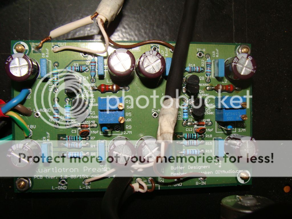
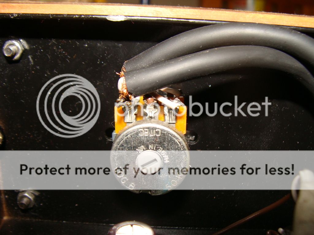
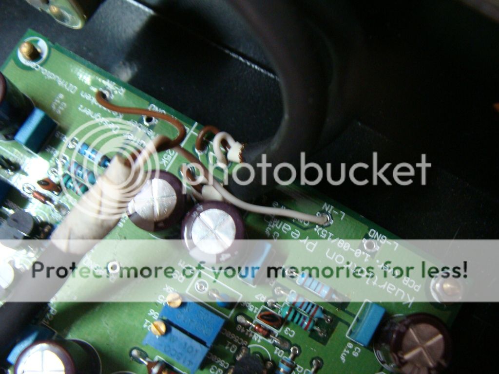
it might be a good idea to use shielded wires for signal since you dont have a metal chassis. I dont see a pot... if you are using a triple normal power wire for mains, you can earth atleast the supply ground. how much is that r-core these days...

@doors666...Thanks for the suggestion. As I've placed this buffer before my integrated amp (AVR in stereo mode), I did not place the pot. I kept the pot for future use as soon as I am done with the power amp.

Too good one of the simplest and good looking cabinets :clapping:. DIY to the fullest extent very nice.
Thank u @manniraj [emoji4]
 
Last edited by a moderator:
Hi Om,
Attaching hi-res pictures. By visual inspection, all solders are looking fine. White, Brown & ground wires are soldered firmly on the board and on the pot. Let me know if you need additional pictures.

Complete Board.
DSC04891_zps2bueaclk.jpg


Volume Pot.
DSC04898_zpsl0ivti9t.jpg


Pot connection.
DSC04902_zpszarhoecz.jpg
From the picture, my suspicion turned out correct. The brown and white wires on the volume potentiometer are interchanged for each channel.
Brown wire must be at right hand side and white wire on middle pins.
Regards.

Finished my build last night. This is probably the ugliest Kuartlotron Buffer on the face of earth.
As this is my first DIY audio project, I am super exited about it.
Any DIY starts like this until you recognize your own skill. :)
Btw you did not mention your test results.
 
Last edited by a moderator:
Any DIY starts like this until you recognize your own skill. :)
Thanks a lot.
Btw you did not mention your test results.
I am glad that you asked. I haven't got a chance to listen to it for long hours.

My chain is like this:
Windows PC (as NAS) > Raspberry Pi 2 > Hifiberry Digi+ > Peachtree DAC-iT > K-Buffer > Yamaha AVR (in stereo mode) > Monitor Audio BX2.

I am using some good cables and ICs too.

Now, coming to the experience - I can say I have found some significant differences in SQ.
1. Midrange and Top end is more crisp.
2. Bass is almost the same.
3. Sound stage is almost the same.
4. Imageging is almost the same.

I have to listen to it for some more hours before coming to any conclusion. Maybe the bottolneck is the power supply and the amplifier itself in my chain. Except K-Buffer all other components are running with SMPS power. I am working on LPSU (for everything except PC) and Power amp too to improve overall experience.
 
From the picture, my suspicion turned out correct. The brown and white wires on the volume potentiometer are interchanged for each channel.
Brown wire must be at right hand side and white wire on middle pins.
Regards.

Thanks Om, I will get help from some one and change the pins.

Will the volume level mismatch between L & R, also be fixed with this change ? Will update the test results after changing.

Regards,
Suresh.
 
Thanks Om, I will get help from some one and change the pins.

Will the volume level mismatch between L & R, also be fixed with this change ? Will update the test results after changing.

Regards,
Suresh.
After correction, if you still feel the difference in sound levels of both the channels then we will look further. IMO, it should not come.
 
@Sureshkn: you could also use separate wires for left and right channels for both input and output, instead of combining them into a single balanced cable. It will help improve inter channel crosstalk.
 
Finished my build last night. This is probably the ugliest Kuartlotron Buffer on the face of earth.
As this is my first DIY audio project, I am super exited about it.

Am i the Only One who is unable to see the Photos?
 
Last edited by a moderator:
i had placed order for R Core 12-0-12 , 1.25A from EMD and was delivered promptly in the past week.

and yesterday received the PSU and K Buffer kit from Sachin! perfect timing of the weekend!

thanks to Sachin every part had been properly marked and board itself has indications for values and polarity!

PSU board:
A1IMG_20160404_031949_HDR.jpg


K Buffer :
A4IMG_20160404_032241.jpg


however, at the end i was left with these trimmers [100R and 5K]: hence the board is not complete yet.

IMG_20160404_032537.jpg

i can see two trimmers in Nikhil's build [superb case that is! congrats!] but in case of Saikat's build it has a resistor for 56R and a trimmer.

my guess is 100R is meant for 56R and 5K one is for 3.6K [which i am yet to solder on]. Sachin, can you please confirm?
 
after few hiccups my K buffer started working this morning!!
together with source selector it works like a charm! [this is my first DIY attempt in audio!]

i have paired it with input source selector module along with motorized ALPS RK27 10K pot. volume tracking is smooth and response is there throughout the turn.


initial impressions are good. i find that there is greater emphasis on high and mid frequencies. music sounds crisp. not sure if this has a burn-in period, but i'm already liking the output. i was worried that being unity gain preamp, it might lead slight decrease in volume output [my Muse DAC RCA outputs are low in volume]. but loudness remains the same.

i still have some work in putting it together in the amp chassis [nothing fancy, just a crude steel amp chassis].

now for the issue: i can hear loud pops from my speaker whenever the unit is turned on/off with the speakers powered on? what could be the issue? any solution for this? for now i switch it on/off last [after powering down my monitors].

and finally thanks to the forum members Sachin, Omishra and Joshua [this thread - those clear pictures and guide on how to tune the buffer made it easy for me]. special thanks to Saikat for responding to my queries and helping me with PSU guide.

It's great to know that everything is working properly. Congratulations on your first DIY build.

Sent from my Nexus 5 using Tapatalk
 
Turn volume knob to zero when switching on/off the amp.

The K buffer is DC coupled, so there is NO capacitor in the signal path to suppress impulses which are invariable when switching on or off the unit. If you have source selector in the buffer, and need to switch sources, turn volume knob to zero when switching.
 
@Saikat thanks! :)

@Joshua , thanks! after returning home i was listening to music and in between while listening, i heard popping sound and after some time left channel stopped playing. i inspected the Buffer board for any shorts or any such stuff. couldn't find any issue. i re-soldered few points and restarted the Buffer - it is working fine now! hopefully it stays that way [my soldering is not great :( ] : praying:


Also can I use the 24V DC output of the PSU board? this is the board designed by Omishra for DCB1. in the PSU manual -for 12V-0-12V secondaries- it is indicated that we can not use 24V output. but i can see 13V DC at this point!!
i need a DC input for power button LED :D

PS: in the course of checking b/w buffer and direct output of DAC during this time, i could clearly feel the difference in music for better [more musical!!]
 
Yes, you can certainly use 24V output for powering front panel LED indicator, or on/off switch's lamp. On my K buffer I use it to power the on/off switch lamp (need to check exact voltage I had set for this) and on DCB1 I use it to power front panel LED (I connected a resistor in series to drop some voltage).

Regarding sound stopping on one channel, do recheck your soldering points, especially if you're using solid core wire for internal wiring, as solid core wires are much more vulnerable to have dry solder compared to multi stranded wires. I have had similar problem many times when I was using CAT6 wires for internal cabling.
 
Last edited:
What a coincidence, I logged in to raise the same question to use power from the PSU for source selector , led power switch and motorized volume control.

Can all three draw current from same PSU ??
 
Can all three draw current from same PSU ??

What are voltage requirements of source selector, etc?

The OPS has two adjustable DC supplies, first the +/-15V which you have probably already adjusted to +/-10V for the K buffer. Second supply is +/-24V which you can adjust to suit source selector. This voltage can also be used to light up LED (you may have to wire a resistor of appropriate value and higher wattage rating to drop some voltage). I'm not sure about the motor of vol control. What is the supply voltage needed for it and how much mW?
 
Wharfedale Linton Heritage Speakers in Walnut finish at a Special Offer Price. BUY now before the price increase.
Back
Top