Batery powered DIY CNC phono stage

Re: Battery powered DIY CNC phono stage

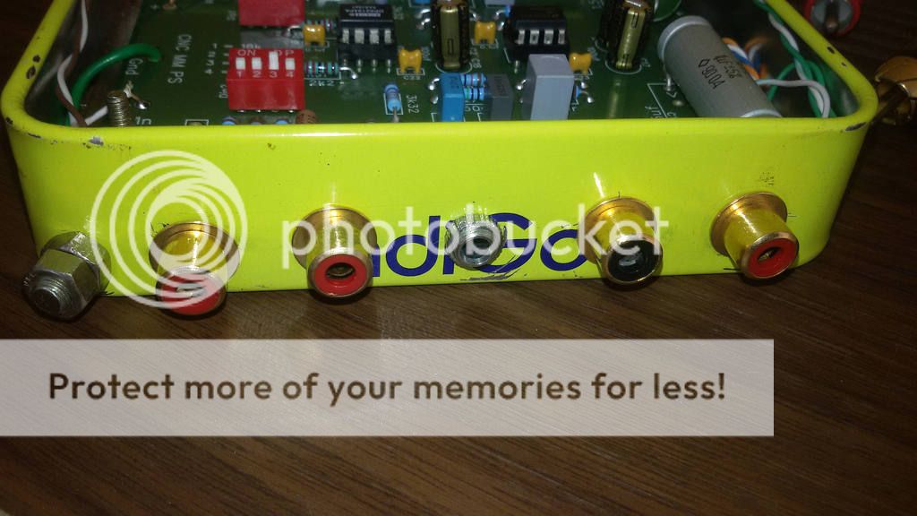
Great points, it works. In the first instance, brother is using a CNC (sachu version) with a 24 volts single rail polycom phone regulated powersupply wired with the same logic. In the second instance, I have tried it with regulation only using 7815 and 7915 regulators, using a 12 volts, 500 ma tranny. The output was 15-0-15.


If you are happy then its fine.
I felt hum noise was more with scheme 1 and for 2, you must have minimum 2.5V difference between input and output. Input mean lower level of ripple. You are measuring peak. No ripple,
12V transformer gives 13.2V unloaded, will result into 18.66V at output with ripple factor it would be 15.5. So regulation could be dependant on capacitor bank discharge rate. This was my point. With load this changes drastically.
Phono stages are notorious in picking hum though CNC is OPAMP based which has higher PSRR. it will will show up.
 
Re: Battery powered DIY CNC phono stage

If you are happy then its fine.
I felt hum noise was more with scheme 1 and for 2, you must have minimum 2.5V difference between input and output. Input mean lower level of ripple. You are measuring peak. No ripple,
12V transformer gives 13.2V unloaded, will result into 18.66V at output with ripple factor it would be 15.5. So regulation could be dependant on capacitor bank discharge rate. This was my point. With load this changes drastically.
Phono stages are notorious in picking hum though CNC is OPAMP based which has higher PSRR. it will will show up.

Agree on the above. I am not sure about the performance element as I have not actually listened to it. Shall run a check and reply with photos.
 
Thanks a lot Sachin and Ragunadh for helping me with the CNC build. Sounding really nice with my naim Nait 5i & PMC set up along with Technics 1210 MK2 turntable.

Apologies for the lazy pictures..
 

Attachments

  • DSC_0169.jpg
    DSC_0169.jpg
    7.5 KB · Views: 212
  • DSC_0172.jpg
    DSC_0172.jpg
    8.4 KB · Views: 213
  • DSC_0173.jpg
    DSC_0173.jpg
    7.8 KB · Views: 212
  • DSC_0175.jpg
    DSC_0175.jpg
    12.4 KB · Views: 216
Last edited:
Hi vinyl lovers,

I need a bit of an expert help.

I am building a CNC phono stage and then would like one like this for MC cartridges going into the same enclosure.

I would switch between the two with a switch powering either of them.

Since both would use high quality (big size, not cheap) output caps, I'm just wandering if I could just share the same caps by switching them between the two. Can we put a switch into the signal path without effecting SQ?

What would be the best way to do this if any? With a 3 or 4PDT switch or a relay?
Could I use the same switch that switches power between the two preamps?

I need advise from you who might have done it already.

Thanks,
Bela
 
You can put switch into output signal path of PCB and after simple DPDT switch you can solder those output capacitors commonly on RCA itself.

Just move shunt resistances of output (100K ?) and DC blocking capacitors directly on RCA after switch. I won't suggest switching input by any means because I noise control is difficult in that case. Still people tried it varying results.
 
Thanks Omishra,

Do I have to move the shunt resistors after the 4PDT switch as well? Why is it?

As I explained I want to share the DC blocking output capacitors between two amps (CNC and one for MC that I have not picked yet) that might have different shunt resistors so these should stay on the PCBs.

I do not want to switch inputs.

I want to switch the power and outputs only between the two amps by using a 4PDT ON-OFF-ON switch.

Please see sketch.

2015-09-07 16.10.06.jpg


Thanks,
Bela
 
Re: Battery powered DIY CNC phono stage

You need those resistance to avoid pop n clicks while using switch. It keeps other side reference to ground .
 
As a response to this thread:
http://www.hifivision.com/wanted/60090-cnc-phono-stage.html
I got a nicely soldered CNC board from Shri Sachin.

Last night I wired up the board. Drilled a few holes in a "Nut Case" tin box, fitted RCA sockets and installed the board for trials. This is a temporary setup to get all the adjustments right before installing it inside a vintage Sansui receiver.

The CNC board is very well made. The PCB designer has taken care to logically follow the schematic while laying out the tracks. I was pleasantly surprised to see Russian PIO caps. I was not expecting this and had a set of vintage oil caps ready for this.

After wiring up, the board worked right away. I had installed LME49720 in both the sockets. But it sounded a little compressed. Then the first socket LME49720 was replaced by OPA2134 and immediately it sounded better. It is still a bit edgy buy I expect after 15 hours it will open up.

So far its good. Here are some pics of my Nut Case CNC phono.

20150919_114250_zpsgdkghxyr.jpg


20150919_114559_zpspvtjybdp.jpg


20150919_114435_zpssdaulwku.jpg
 
Nice one, I've too have built one for a friend using a similar cashew nut tin box which I usually get on indigo flights.
Yes indeed the tin box is ideal. It provides the best possible shielding. Hum and RFI is absolutely zero with the inputs shorted.

My batteries ran out on the 2nd day. Must have clocked max 20 hours. Is this usual drain rate? When we started batteries read 9.5 volt. Now its about 4.5 volt but the CNC refuses to power up. I will get a pair of 12 volt lantern batteries today or rig up a proper PSU.
 
As a response to this thread:
http://www.hifivision.com/wanted/60090-cnc-phono-stage.html
I got a nicely soldered CNC board from Shri Sachin.

Last night I wired up the board. Drilled a few holes in a "Nut Case" tin box, fitted RCA sockets and installed the board for trials. This is a temporary setup to get all the adjustments right before installing it inside a vintage Sansui receiver.

The CNC board is very well made. The PCB designer has taken care to logically follow the schematic while laying out the tracks. I was pleasantly surprised to see Russian PIO caps. I was not expecting this and had a set of vintage oil caps ready for this.

After wiring up, the board worked right away. I had installed LME49720 in both the sockets. But it sounded a little compressed. Then the first socket LME49720 was replaced by OPA2134 and immediately it sounded better. It is still a bit edgy buy I expect after 15 hours it will open up.

So far its good. Here are some pics of my Nut Case CNC phono.

20150919_114250_zpsgdkghxyr.jpg


20150919_114559_zpspvtjybdp.jpg


20150919_114435_zpssdaulwku.jpg
Congrats Sir. Finally you got the CNC. The Russian PIOs are a pleasant surprise. I have been researching up on a few of these like KBG, K40-Y9, K42-Y2,etc. I absolutely have had a fantastic experience with the K40-Y9 (0.47uf) in my DAC as well as with my super tweeters (.47, 1, 1.5, 2.2uf). These bring richness and lushness to the tone. If doing a direct comparison with electrolytic caps, these could appear to mask fine details, but these certainly do make up for in the rich & warm tone. I might plan some KBGs for my main speaker crossover.
 
I used to get 35-40 hrs of playing time with batteries, but sometimes only 10-15 hrs. I used to use cheap Chinese batteries. They were not reliable.
I am now running it on regulated power supply with adjustable output voltage. I have found that some opamps sound better with increased voltage like +/-12V or +/-15V

Regards
Sachin
 
There are not many measurements (if any) of this circuit. While all of us who have built it can testify that it's very good, there hasn't been a way of telling how good.

I just got a QuantAsylum QA400 audio analyzer, so I thought I'd share my findings with you.

The measurements are with a 1 kHz sine in and an output of 1 Vrms from the CNC, with a bandwidth from 10 to 20.000 Hz. As it stands, I'd need a decent inverse RIAA circuit to measure through the whole bandwidth.

This is a CNC with OPA2134 and +/- 15V PSU (LM317/337). No out of the ordinary components, just WIMA MKS2 caps and standard 0.25W/1% resistors.

THD: 0.00190%
THD+N: 0.01013%
SNR: 80,6 dB
IMD: 0.0195% (ITU-R 19+20 kHz)
Dynamic Range: >100 dB (THD+N: 1%)
RIAA Compliance: +/- 0.025 dB

The dynamic range can't be determined without an attenuator, as the QA400 goes into clipping long before the THD+N increases by more than 0.01%.

I'll measure crosstalk as well, when I find time for it.


-skrodahl

Audiobah TPA3116 || ESP P88 || ProJect Debut Carbon Espirit DC || Muffsy Phono Preamp PP-3 || RuneAudio / RaspBerry Pi / HifiBerry DAC || Dynaco A25

That seems to be good data for phono Preamplifier. Definitely encouraging news for DIY :)
 
That seems to be good data for phono Preamplifier. Definitely encouraging news for DIY :)

The numbers are quite encouraging. I just found out that I'm not measuring signal to noise ratio (SNR) correctly, it should be done with the inputs shorted. Signal-to-noise Ratio (SNR), Dynamic Range, and Noise

With the inputs shorted, the SNR (relative to the 1 Vrms/0 dBV signal) is 112.83 dB. The dynamic range has got to be equal to, or greater than that. I'm not sure that it matters that much when we're looking at values greater than 110 dB.

Here are the updated specs:

THD: 0.00190%
THD+N: 0.01013%
SNR: 112.83 dB (Inputs shorted, relative to 0 dBV/1 Vrms)
IMD: 0.0195% (ITU-R 19+20 kHz)
Dynamic Range: >110 dB (THD+N: 1%)
RIAA Compliance: +/- 0.025 dB

I'd say those are some respectable values. :)
 
Last edited:
Crosstalk measurements are in, at -75.58 dB. I've also done some work to get a proper test environment, and THD fell to below 0.0008 dB. At these levels, the readings are fluctuating somewhat. The presented specs are a decent average representation of the measurements:

THD: 0.00190%
THD+N: 0.01013%
SNR: 112.83 dB (Inputs shorted, relative to 0 dBV/1 Vrms)
Crosstalk: -75.58 dB
IMD: 0.0195% (ITU-R 19+20 kHz)
Dynamic Range: >110 dB (THD+N: 1%)
 
When measured crosstalk, I initially got a reading of -75.58 dB. That's also quite a good value, but I expected it to better.

It turns out that there is quite a bit of input coupling. When I shorted the input, the crosstalk is -102.24 dB. That's very good, and what an opamp-based circuit should have.
 
Last edited:
I have measured the RIAA curve manually, and found the deviation from the ideal curve:


The circuit measures +0.32/-0.02 dB across the audio band. The negative deviance is only -0.02 dB, which is actually within the stated specifications. The +0.32 dB is at 80 Hz. The rest of the extra amplification is at 150 Hz and below, giving an ever so slightly improved bass. Knowing how much the bass can be attenuated on an actual record, this is only a good thing.

There is only one small 0.11 dB hump at 2 kHz. Except for that, the phono stage actually measures within the stated specifications of +/- 0.025 dB.
 
hi Skrodahl,
while i understand that this may be highly op amp dependent, do you have any numbers on the PSRR/ hum for the specific device you tested?
 
Follow HiFiMART on Instagram for offers, deals and FREE giveaways!
Back
Top