Batery powered DIY CNC phono stage

I am Zero in DIY, whom can I approach for a CNC build in Hyderabad? What will be the ballpark figure of the completed build?

It is a little difficult to quote a ball park figure for the CNC as there are a wide variety of combinations available. For example, you can build one like specimen-A for as little as Rs.200/- or you can build one like specimen-B for around Rs.3500/- (depending on the type of OP amp and quality of components used). Though specimen-A will give you great results and will completely shock you with its outstanding performance, if you are a seasoned vinyl enthusiast with above average equipment (which will help show up the difference), then the variety offered by Sachin is the absolute best.

Specimen-A

DSC07212_zps73e2a3ce.jpg


DSC07213_zpsfb35fb0a.jpg


Specimen-B

WP_20160703_14_55_24_Pro_zpsshwmcgsc.jpg


WP_20160703_14_55_12_Pro_zpsxygidmiz.jpg
 
You should have a very good Bass

The CNC should sound nice right out of the box. Instruments and bass is good from word go.

I have built many versions of the CNC, the main one being the Sachu version. Never noticed any problem with the bass right from the very first minute of operation.

Figured out what the issue was.. I should thank god on this sabbath day for HFV being a digital forum, else, I deserve to be thrashed for the blunder I overlooked.

Well, The BASS was missing because..
.
.
.
.
.
..
....
......
The sub-woofer setting in line-in was turned on in the AVR but I do not have a sub-woofer. I turned off the sub-woofer and everything turned magical. I still get a lot of hum. I think it is because of the shabby work with the cabinet, RCA terminals and grounding... Will post pics and seek assistance.

Thanks all!! :clapping:
 
I still get a lot of hum. I think it is because of the shabby work with the cabinet, RCA terminals and grounding... Will post pics and seek assistance.

Thanks all!! :clapping:

Have you connected the TT ground to phonostage?
There could be a problem with your TTs RCA cable.

Regards
Sachin
 
Please find the pictures in the link: https://www.flickr.com/photos/88451104@N00/?
I am connecting the TT ground, ground from the mains to the same screw in the cabinet. Also, the RCA's metal body is touching the cabinet (metal washer, the negative line to the phonostage etc). Could this be the reason for the hum that I am getting?

If it is because of RCA, then, I would have to use another set of RCA terminals (one in red colour): https://www.flickr.com/photos/88451104@N00/29131810623/. You would notice on this pic that negative for both right and left are merged into a single row (the row behind). If I were to use these terminals, is it okay to connect the negatives of both the changes to the same place? Please advise.
Your RCA's should be isolated from metal cab. I would also suggest you to use separate ground from Phonostage board to TT. You can use Banana connector for it.

Regards
Sachin
 
From my experience, your choice of wires for the input and output wiring is incorrect. Always used good quality single core shielded wire for input and output wiring. I have used orange dual core microphone cabling in my version of the CNC built to exact Sachin specs :) (pictured in the HDD case, a few threads back). You can get good results with single core shielded wire, like the one pictured below:

ws01z.jpg


Also ensure that the ground wire of each of the RCAs (both input and output) are wired to their respective ground points on the PCB, individually. This is very important as ground loops can cause irritating hum. The picture below (although in a different context) will explain what a ground loop is:

grounding.png


Of course, outside of this, you'd also need a separate ground connection wired from the PCB to the chassis of your turntable (or to your tonearm chassis if you use a stand alone tonearm), as explained by Sachin.

I would have taken the shielding to the next level by isolating the Power supply from the phonostage with a simple grounded metallic barrier or sub-enclosure (which can be made from thick tin foil which you can salvage from fast food take-away packaging).
 
Last edited:
From my experience, your choice of wires for the input and output wiring is incorrect.
As an after thought, I too think so. I used the wires from SMPS. I have unsoldered and soldered the wires three times now and am comfortable doing it !!! I have some unbranded interconnects but remember it has some shielding. It wasn't single core though. I shall check; else I shall buy a meter.

Of course, outside of this, you'd also need a separate ground connection wired from the PCB to the chassis of your turntable (or to your tonearm chassis if you use a stand alone tonearm), as explained by Sachin.
It is the grounding which holding me hostage as I am unable to comprehend the science. The image that you provided, explains it better. But, when I try think about it alone, it is always an out of syllabus question.:eek:

I would have to wait until next weekend to get a banana connector to connect TT's ground wire. For now, I have connected phonostage ground and TT ground to a nut placed in the cabinet.

I would have taken the shielding to the next level by isolating the Power supply from the phonostage with a simple grounded metallic barrier or sub-enclosure (which can be made from thick tin foil which you can salvage from fast food take-away packaging).

Tin foil is the easiest thing I can do for now. I can live with the hum as it is not that obtrusive after I can changed RCA terminals to avoid contact with the cab.

Thanks for all your detailed tips! They have been very helpful. I would have to buy shielded wire and banana connector next week. Until then, I shall focus on the cosmetics.
 
Also noted that you have used a 3-way AC mains cord with the AC inlet earth pin grounded with the chassis. Though this is theoretically correct, you may want to isolate the AC earthing from your CNC grounding and check the results.
 
Kindly go through post #168 here: http://www.hifivision.com/diy/59385-kuartlotron-error-correcting-super-buffer-17.html to get general idea on how to wire up line level buffer/preamp/phono preamp.

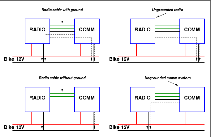
As Sachin mentioned, the first thing not to mix up is the return leads of the RCA input and output sockets WITH the chassis. Cabinet-mounted RCA sockets come with two plastic washers which are meant to insulate the barrel of the RCA socket as it passes through the hole in the cabinet. This ensures that the signal ground/return and the chassis are NOT at the same electrical potential.

For internal signal cabling my strong recommendation is to use a twisted shielded pair. One of these wires is used for signal positive and the other is obviously the signal negative. The shield of the cable is grounded to the chassis at the source end of the signal path, and kept floating/unconnected at end point of the signal path. To expand on that, assume the cable that connects input RCA socket to your circuit board. The signal flows from RCA socket to PCB. So RCA socket is source in this case, and PCB is the end of the signal flow in this case (we're considering only the segment of signal flow through the cable, and not the complete signal flow). So expose the shield at RCA socket end and short out securely to chassis, and simply cut the shield at the PCB end (marked In+ and In- on the PCB). Similarly, there are a pair of cables from the PCB Out+ and Out- to output RCA sockets. Here the signal starts at the PCB and ends at the output RCA sockets, so short shields at PCB end to chassis, and let shield float at output RCA sockets.

The next thing to take care of is the phono ground point at the PCB. This extends to a screw or binding post on the chassis and must ideally be insulated from the chassis. The phono ground is carried to the turntable by a separate wire.

On the AC power lines that supplies the CNC, the earth must be grounded to equipment chassis and transformer chassis.

There is one further isolation/lift of the power supply, in case you're interested further.

Now, the cables that carry the signal from the turntable to the phono preamp is very, very vulnerable to interferences as the signal is very weak. This is still true even if the cables from turntable to phono preamp are shielded cables. You'll be surprised how much interference gets induced through these cables if run close to other power cables or passed near transformers even when using shielded twisted pairs shielded coax cables. So route the TT's cable as far away from nearby power cables and other electronics like amps.

If you cannot use shielded twisted pairs for internal cabling, use tightly twisted pairs.

Power supply cables inside the cabinet must also be tightly twisted.

Reducing interference in phono preamps is a challenging task at the best of times, so it's best to follow these basic cablng hygienes.
 
Nice suggestions from Joshua and Reuben. Kindly note few points for soldering RCA connectors and wires.
1. Your soldering iron should be very hot.
2. Use flux on wires and pre tint them
3. Use flux on RCA's and pre tint them.
4. Heat pre tinted RCA for few seconds and place pre tinted wire on it, wait for 2-3 seconds, remove soldering iron. You are done.

You can use twisted pairs of CAT5 wires for signal. They are very easy to solder, use only required length.
Also tightly twist power supply and transformer wiring. You can see my build here.
http://audiokarma.org/forums/index....age-build-and-help-desk-thread.501186/page-40

Regards
Sachin
 
Last edited:
Nice suggestions from Joshua and Reuben. Kindly note few points for soldering RCA connectors and wires.
1. Your soldering iron should be very hot.
2. Use flux on wires and pre tint them
3. Use flux on RCA's and pre tint them.
4. Heat pre tinted RCA for few seconds and place pre tinted wire on it, wait for 2-3 seconds, remove soldering iron. You are done.

You can use twisted pairs of CAT5 wires for signal. They are very easy to solder, use only required length.
Also tightly twist power supply and transformer wiring. You can see my build here.
AD797 Phono Stage Build and Help Desk Thread | Page 40 | Audiokarma Home Audio Stereo Discussion Forums

Regards
Sachin

+1
also to add from practical experience, lightly sand the RCA tags and wire ends and make them bright and shiny (you can also use a sharp razor blade for the purpose), then use flux and pre-tint.
 
Nice suggestions from Joshua and Reuben. Kindly note few points for soldering RCA connectors and wires.
1. Your soldering iron should be very hot.
2. Use flux on wires and pre tint them
3. Use flux on RCA's and pre tint them.
4. Heat pre tinted RCA for few seconds and place pre tinted wire on it, wait for 2-3 seconds, remove soldering iron. You are done.
AD797 Phono Stage Build and Help Desk Thread | Page 40 | Audiokarma Home Audio Stereo Discussion Forums

Regards
Sachin

I apply flux and pre-tint the connectors before soldering. I am comfortable with the soldering.

You can use twisted pairs of CAT5 wires for signal. They are very easy to solder, use only required length.

I have a few LAN cables lying unused. Are these considered as shielded wires, If so, I shall use them.

+1
also to add from practical experience, lightly sand the RCA tags and wire ends and make them bright and shiny (you can also use a sharp razor blade for the purpose), then use flux and pre-tint.

My dad asked me to scratch the tags before soldering; I didn't do so as I thought they were new and should be good. I see the wisdom in doing so now.

I shall spend time this weekend to fix the wiring and grounding.
 
LAN cables are CAT 5, they are not shielded.Twist them tightly and use required length. They are very good for signal.

Regards
Sachin
 
If using CAT wires please scrape/sandpaper the points to be soldered for better contact. Personally I've had lots of bad contact troubles with solid core wires mainly due to my own poor soldering practices, but I absolutely love the way they sound.
 
I got microphone shielded cables for the ins and outs; that removed hiss quite a bit. Now after a few weeks the phonostage's volume has gone down significantly. Any pointers as to why such a thing should happen? Please let me know where to start.
 
Hello everyone,
I came across to this forum while searching for a good phono preamp circuits. I found this CNC Phono stage very interesting. Where can I buy a PCB for this? Muffsy is not selling bare PCB anymore. Thanks.
 
For excellent sound that won't break the bank, the 5 Star Award Winning Wharfedale Diamond 12.1 Bookshelf Speakers is the one to consider!
Back
Top