.
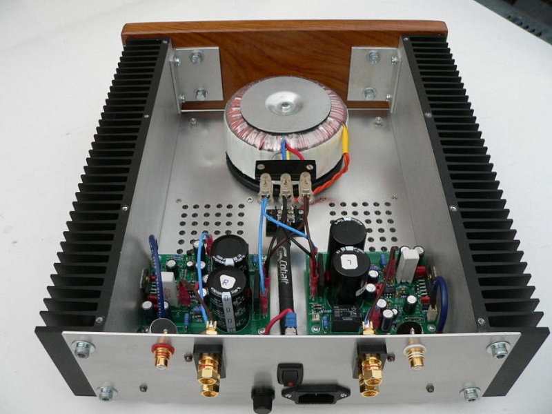
~ Is layout of above casing and pcb arrangement OK ?
~ Can we use Computer CPU Heatsink ?
~ What value volume pot is needed ?
~ Can we move volume pot near volume knob behind front panel ?
~ Does LM3886 Chip require any insulation while fixing it on heatsink ?
~ Will this amp require earth wire from AC power in ?
~ Which wires will be good for Line in and line out ?
~ Can we ground the metal casing so there is less interference ?
There are few errors in the connection diagram.
1) What has been labeled as LINE-OUT is actually SPEAKER-OUT, i.e. power output.
2) The connections from the transformer go to the connectors on the PCB which are labeled as AC1, PGND and AC2 (24-0-24) respectively, and not as shown.
You can use PC processor heatsinks if you can drill and mount it accordingly.
IIRC, the suggested value of the volume pot was 25k, but anything between 10k and 50k will probably work. Check the DIYaudio thread for details.
The volume pot can be on the front panel (that's where it usually is), but you'll need to shield the line-in cables carefully to avoid pick-up and hum.
The LM3886TF chip with isolated plastic package does not need insulation. The LM3886T with metal-tab needs to be insulated with a mica insulator or similar. I will be supplying the TF version only with the kit - it's safer.
The earth wire from the AC power line needs to be connected to the chassis ground, also known as the safety ground. The safety ground can be (optionally) connected to the amplifier power ground (PGND) through a CL60 isolator, or the PGND can simply be left floating.
For LINE-IN, you can use a shielded single-core cable for each channel.
For LINE-OUT (actually, SPEAKER-OUT), you can use standard speaker wire (this is usually transparent plastic insulated wire, with one core being bare copper (red) and the other core being tinned copper (gray), to indicate polarity. The tinned side goes to speaker ground (-), while the copper side goes to speaker (+).
Yes, you need to ground the metal chassis for safety - this will avoid an electric shock if by chance the live primary-side winding of the transformer accidentally shorts to the metal core and hence to the chassis.


") Hi Everyone,
Hi Everyone,