You are using an out of date browser. It may not display this or other websites correctly.
You should upgrade or use an alternative browser.
You should upgrade or use an alternative browser.
Mauro's "Myreference Rev.C" building queries and guide.
- Thread starter Hiten
- Start date

"The power supply of the tested amplifier is +/-24 volts and should be rated at 6 amps continuous duty, and more than 10 amps peak per channel"
Is this talking about PSU rectification circuit or the Trafo itself? In either case if I get a 24-0-24 6A Trafo will it it work with GC safely, considering GC requires 5A?
I'm not an expert on the F5, but considering that it is Class-A, I'm guessing that it requires +/- 24 V *rectified DC*, i.e. lower than the +/- 32 V rectified DC of the MyRef. Note that the F5 heatsinks will still have to dissipate about 288W/2-ch at quiescence even at +/- 24V, 6A.
For the MyRef, 24-0-24, 6A will work fine. Anything in the range of 22-0-22 to 25-0-25, 4.5A to 6A should work. If you want a little additional current margin, go for 6A.
How has using LM3886 as current pump and LM318 as volt amplifier benefitted this topology ?
From the simulations, the main advantage was stability into difficult loads. Since the compensation networks are mainly centered around the LM318, it's possible to stabilize the circuit independent of the LM3886 Howland current-pump and make it unconditionally stable even into pure capacitive loads like electrostatic drivers.
The unexpected added benefit of the topology is that the sonics of the combined amp are those of the LM318 - which is a high slew-rate, respectably fast op-amp with excellent sonics, but limited drive capability. With the LM3886, the drive capability is enormously increased, so that limitation is removed.
From a practical layout perspective, it's possible to separate out the two sections into large-signal (LM3886) and small-signal (LM318) and isolate the power rails, grounds, signals, etc. of the two sections. With careful small-signal shielding and grounding, the amp becomes very quiet, smooth and dark with little or no EMI/RFI issues.
Hi Linuxguru
~ Can I 'short' two grounds of the volume pot ?
~ Do I need to put any capacitor to power in (to remove on/off thump) ?
~ Are the PCB's of two channels joined ?
~ In future can one replace 10,000 u c3 and c8 caps to improve bass ?
~ If for few months amp is running fine, can one bypass the relay ?
~ What specification speakers one should look for so as they match this amp ?
Hope I am not bothering you too much.
Thanks in advance.
Hi Linuxguru
~ Can I 'short' two grounds of the volume pot ?
~ Do I need to put any capacitor to power in (to remove on/off thump) ?
~ Are the PCB's of two channels joined ?
~ In future can one replace 10,000 u c3 and c8 caps to improve bass ?
~ If for few months amp is running fine, can one bypass the relay ?
~ What specification speakers one should look for so as they match this amp ?
Hope I am not bothering you too much.
Thanks in advance.
I have shorted mine with no issues. I plan to use mine without the volume pot BTW
cheers
~ Can I 'short' two grounds of the volume pot ?
~ Do I need to put any capacitor to power in (to remove on/off thump) ?
~ Are the PCB's of two channels joined ?
~ In future can one replace 10,000 u c3 and c8 caps to improve bass ?
~ If for few months amp is running fine, can one bypass the relay ?
~ What specification speakers one should look for so as they match this amp ?
- It's better to run the two grounds of the volume pot separately to the input connector grounds of the two channels - the channel separation will be better.
- I haven't used a switch spark-suppression capacitor, but it is often used in audio projects. Check out DIYaudio and other places for a suitable circuit.
- The PCBs are separate monoblocks.
- There's space for 35mm diameter capacitors at C3 and C8. Anything that physically fits can be used - at the moment, the largest value I've seen in that diameter is a Panasonic TS-UP 22,000 uF/50V.
- It's mainly a function of how valuable your speakers are. My test speakers are cheap DIY units costing less than Rs.1k/pair, so I completely omitted the protection relay circuit (after checking that the output DC offset was low enough). OTOH, if you're using high-end commercial speakers, it probably pays to retain the protection circuit.
- Any 8-ohms, 40 to 50W unit should be fine. The best bet is a full-range like the 8" Pioneer 'Bofu' or similar, but it will be fine with 2-way or 3-way speakers also. Try not to use high-order crossover networks - a simple capacitive 1st-order network for the tweeter will work fine, and that's what I'm using in my DIY 2-way.
- There's space for 35mm diameter capacitors at C3 and C8. Anything that physically fits can be used - at the moment, the largest value I've seen in that diameter is a Panasonic TS-UP 22,000 uF/50V.
- It's mainly a function of how valuable your speakers are. My test speakers are cheap DIY units costing less than Rs.1k/pair, so I completely omitted the protection relay circuit (after checking that the output DC offset was low enough). OTOH, if you're using high-end commercial speakers, it probably pays to retain the protection circuit.
So you are saying the option is there to add caps but is not part of the original BoM?
I heard they color the sound and people prefer the SQ without.
Thanks
keith_correa
Well-Known Member
What? The caps? If yes, which caps? Or are you referring to the relay circuit?I heard they color the sound and people prefer the SQ without.
Gobble, How will you control the volume ?I plan to use mine without the volume pot BTW
cheers
If you mean capacitors on c3 and c8 they are like reservoirs when loud passages of music comes amp will not have problem. I hope I am rightI heard they color the sound and people prefer the SQ without.
Thanks
 if you mean relay the less contacts in signal path the better that's why I asked if one can remove it.
Last edited:
So you are saying the option is there to add caps but is not part of the original BoM?
I heard they color the sound and people prefer the SQ without.
C3 and C8 are part of the original BOM, and not optional. They're the main PSU filter caps. However, you can choose to change the default value (I'm using 4700uf to 6800uF/50V) to something either smaller or larger - that was the context of the original question.
As to whether C3 and C8 colour the sound, it's certainly going to have an effect on the overall presentation, but it's less important than people imagine. The sonics are more closely governed by the bypass caps, especially around the LM318.
Gobble, How will you control the volume ?
If you mean capacitors on c3 and c8 they are like reservoirs when loud passages of music comes amp will not have problem. I hope I am right
This is not an integrated is it? I have a preamp
") Umm are you saying this chipamp cannot be used with a pre?
Umm are you saying this chipamp cannot be used with a pre? 
Edit: Can the gain on this thingie be tweaked/adjusted to work better with my pre if needed?
Cheers
Last edited:
Sorry Gobble I misunderstood. I thought you were directly connecting it to source (CD Player) Yes you dont need volume control. as this post says...
It's only a power amp board with a single, high-Z (100k) input. You can couple any line-level signal of about 0.5-0.8 V (peak) into it. I use the line output of an Audigy 2 soundcard, for instance, to test it.
There is no pre-amplifier on board, so you can use an external pre- if you wish. There's no need for it in practice, unless you want tone controls.
Sorry Gobble I misunderstood. I thought you were directly connecting it to source (CD Player) Yes you dont need volume control. as this post says...
Yep, but thanks for the heads up - a quick search and everybody seems ot be complaining about too much gain with the GC paired with a preamp. Meaning it will be too loud even at low turns of the volume pot ...
I may need to tweak the gain a bit. My pre offers 14db gain.
And I want the tube coloration
Siva??
Thanks
I'm not an expert on the F5, but considering that it is Class-A, I'm guessing that it requires +/- 24 V *rectified DC*, i.e. lower than the +/- 32 V rectified DC of the MyRef. Note that the F5 heatsinks will still have to dissipate about 288W/2-ch at quiescence even at +/- 24V, 6A.
For the MyRef, 24-0-24, 6A will work fine. Anything in the range of 22-0-22 to 25-0-25, 4.5A to 6A should work. If you want a little additional current margin, go for 6A.
It seems the F5 requires a trafo with 18v to 20V not accounting for regulation.
I will check if it works with 22-0-22 that should be close.
Quick question - does rms per channel translate to gain provided by the power amp? I need a GC with a lower gain to work with my pre anyways, if so the lower specs of 22-0-22 for GC will work in my favor then.
Thanks
.
Quick question - does rms per channel translate to gain provided by the power amp? I need a GC with a lower gain to work with my pre anyways, if so the lower specs of 22-0-22 for GC will work in my favor then.
No, the gain is fixed at ~32 in the MyRef, and can't be changed easily without affecting the compensation networks.
The max RMS power per channel is largely governed by the rail voltages.
If you need lower overall gain, then you'll need an input attenuator or a volume control.
Y
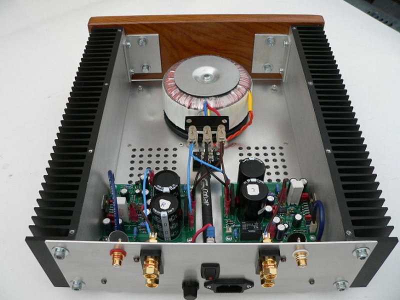
If I make another one, I would probably build it similar to this one -
capt rajesh,saikat and a few others have asked whether i can build an amp chasis
though ive started some designing on the basis of tthe following website modu
the chasis in the above pic with the oversized heatsinks can also be executed with the hardware (binding posts,RCA's,IEC power socket and power swithch and possibly a milled volume knob )
is anyone seriously intrested?
i ask because you must understand that such a chasis with this level of finish is not cheap(especially considering those huge sinks)
Also if this chasis is built i dont know the technicalities oh how you would place your PCB wrt to the heatsink
is it possible? - i mean placing your PCB;s after the chasis is built with the sinks
do you have to mount the sinks ON the PCB , next to it - i dont know
Yes! Yes! Yes! Yes!
hyeah:hyeah:hyeah:hyeah:That chassis is for the F5 looks like not the GC. I have seen that on an F5 thread.
Cheers
No, the gain is fixed at ~32 in the MyRef, and can't be changed easily without affecting the compensation networks.
The max RMS power per channel is largely governed by the rail voltages.
If you need lower overall gain, then you'll need an input attenuator or a volume control.
So use two volume pots? one on my preamp and one on the GC?
I love turning knobs and dials oooh! :licklips: I am loving it already!!
hyeah: People advice a unity gain buffer with this one. And it seems the Nova Peach Tree is nothing but a DAC + tube unity gain buffer + inverted chipamp combo in a lovely box.
Maybe Magma should replicate the Nova finish and create a scare in the market
")
Cheers
Last edited:
Buy from India's official online dealer!
Similar threads
- Replies
- 3
- Views
- 17K
- Replies
- 28
- Views
- 8K
- Replies
- 16
- Views
- 13K