(Another) Pearl 2 Buiild

jls001

Well-Known Member
Joined
Feb 9, 2010
Messages
6,180
Points
113
Location
Mumbai
Forking from here so as not to clutter the original thread there and to keep this separate.


I started my Pearl II build last evening. Here is my meagre achievement:


4mg2.jpg


I concentrated on populating 0.1 uF capacitors as the count per monoblock board was unusually high (11 per side). I faced an unexpected problem: the physical size of the capacitor was larger than the allotted slot on the board. So I ended up doing a delicate jugglery to accomodate the capacitors as shown in the photo below:


iq16.jpg


Parts count is very high, so progress is slow. I will use the 22-0-22 R-Core transformer for the PS section, like svaze's build.

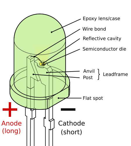
Question: Though I haven't reached it yet, I can see an LED lamp. How do I determine the correct terminals on the LED? On the board, one side of the circle is flattened so I am assuming it means something? I know that if I put it the wrong way, it should be equivalent to an open circuit, but that's discovering the correct leads the crude way.
 
Yes Sachin bought 150V rating caps in place of 63V, so footprint increased. Still no issues.

How do I determine the correct terminals on the LED?
Observe the circle area of LED on PCB. It has flat line cut at lower end above letters "Red 5mm". There you have to match base of LED which is also same flat edge.

e.g.
450px-LED%2C_5mm%2C_green_%28en%29.svg.png
 
Last edited:
Some progress made last night - almost completed populating the mono boards with the small parts. Large parts like capacitors saved for last.

A WIP pic here:

4g9f.jpg


Questions for Om, svaze, bhaskarcan, Sachin and other who have completed this build:

1) On the input side, there is a slot for a resistor marked as "R*". What should be this value?

fyas.jpg


2) On the output side, there is a resistor marked "Rx" and a capacitor marked as "Cx". What are the values of these parts?

0yeb.jpg


3) The 2SK170 JFETs come in double layered aluminium foils (befitting jewellery:lol:), packed in pairs. Are these matched pairs? If yes, what is the correct placement on the board - there are six per side - Q6, Q7, Q8, and Q9 in input section, and Q4 and Q5 near output.

4) I understand one needs to use heatsink for the 7824 and 7924 regulators. Do we need heatsink for the MUR860 as well on the PS board?

5) I bought this heatsink (below pic, not yet soldered). The form factor is different from the one on the board. Will it be sufficient to dissipate the heat build up? It works without obstructing anything on the main board but doesn't leave room for the 0.1 uF caps on the PS board. If I must use heat sinks on the MUR860s, then it will need another trek to the market (and a long search, which I am wary of).

0w4l.jpg


Thanks in advance.

A learning: I was using the fancy new silver solder a fellow forumer got me sometime back. Well, when the surface area on the solder side of the board is small, it is a real pain to get it to stick. I was using my trusty Soldron soldering rod (this rod has soldered on for nearly two decades:clapping:). I finally had to whip out the fine-tipped Goot soldering rod which I hate using because of the fine tip (except for soldering tiny parts), but that didn't cut it either. Finally, a regular solder did the trick:)

Silver schmilver.
 
Hi Joshua, be careful about the LED soldering, when I first powered on my Pearl II it smoked near the reg across the 7924 regulator and that was due to the incorrect soldering of LED as figured out during the debugging done by Mishra sir.
 
I will be following this thread avidly.
Do tell us what your total cost and time spent is once you've finished!:)
 
2) On the output side, there is a resistor marked "Rx" and a capacitor marked as "Cx". What are the values of these parts?

3) The 2SK170 JFETs come in double layered aluminium foils (befitting jewellery:lol:), packed in pairs. Are these matched pairs? If yes, what is the correct placement on the board - there are six per side - Q6, Q7, Q8, and Q9 in input section, and Q4 and Q5 near output.

A learning: I was using the fancy new silver solder a fellow forumer got me sometime back. Well, when the surface area on the solder side of the board is small, it is a real pain to get it to stick. I was using my trusty Soldron soldering rod (this rod has soldered on for nearly two decades:clapping:). I finally had to whip out the fine-tipped Goot soldering rod which I hate using because of the fine tip (except for soldering tiny parts), but that didn't cut it either. Finally, a regular solder did the trick:)

Silver schmilver.

Hi Joshua,
Rx is a gain resister.You will need it if you want additional gain.Pearl2 gain in 55db,already very high.You will need to short it with jumper.Please leave Cx position blank(don't short it)
Jfets are closely matched quads.Please use 6 per side.
Silver slder is not good for DIY.It needs higher melting temperature,and very hard to remove if something goes wrong.60-40 is good,but 63-37 is best.I have bought CARDAS Quad Eutectic Solder from Ebay recently and it works better than anything else I have used in past. Cardas Quad Eutectic Solder 10 FT Length | eBay

Regards,
Sachin
 
4) I understand one needs to use heatsink for the 7824 and 7924 regulators. Do we need heatsink for the MUR860 as well on the PS board?

5) I bought this heatsink (below pic, not yet soldered). The form factor is different from the one on the board. Will it be sufficient to dissipate the heat build up? It works without obstructing anything on the main board but doesn't leave room for the 0.1 uF caps on the PS board. If I must use heat sinks on the MUR860s, then it will need another trek to the market (and a long search, which I am wary of).

Hi Joshua,
You don't ned any heatsink for MUR diodes.This heatsink is sufficient to dissipate heat from regulators.

Regards,
Sachin
 
R15, Rx = shorted with jumper
C15, Cx = open
C7, 10pF = not used, open

R20 R* => Purpose of R*, near input is for adding MM/MC switchable loading. For normal MM operation R20 is open and R19 (47.5K) is in action. For direct MC cart connection (without SUT) you can use R* as 3 times of DC resistance of cart. e.g. For Denon DL-103 R20 could be ~300? and 103R it could be 120?. Make it in and out using switch on one terminal of R20 which connects to ground line below.
 
Last edited:
Thanks for the inputs, Om and Sachin. I had populated the electrolytics on all three boards, so only the FETs and regulator ICs are now pending. If I fit those, then I guess I am ready to test the circuitry. I also need to carefully wire up the mains to the transformer via the IEC/switch/fuse to PS board.

I plan to use Bibin's cabinet to house this build. Now I need a smallish cabinet to house the PS unit. Finding this is again gonna be a tough one, but in the meantime I will have to dedicate one large, unused aluminium cabinet for this function.

I already have:
1) 4-pin DIN connector for connecting umbilical from PSU to main circuit (one can use even XLR socket but I thought it may cause unnecessary confusion),
2) two pairs of Neutrik RCA sockets,
3) IEC socket with switch and fuse (MX, IIRC),
4) speaker banana socket and jack (MX, gold plated) - as ground terminal
5) shielded coax cables (Toyo brand) for internal signal cablings (like board to RCA socket)
6) tinned copper cables of about 14 AWG (my guesstimate) with teflon insulation for power-related internal wirings
 
IF you are afraid of handling mains then find AC adapter of 22-24V. Hook its output to PS board at one of (~AC, either J1 or J3) and other 0V(CT) - J2. Further stuff will remain same and mains will be away from PS. Add ferrite bead on PS wire.
But Adapter must be giving output 22-24VAC,1000mA min and NOT DC.
 
Last edited:
Completed populating the boards. Indisposed since Friday night so unable to make further progress.
 
Some pictorial updates of the Pearl 2 build:

1) Top view of the Power Supply Unit

iead.jpg


2) R-Core and IEC socket details. In the absence of a proper isolator, note that the ground of the incoming supply is extended directly to the chassis of the R-Core transformer and the cabinet (see the white cable). omishra guided me on how to correctly wire up the IEC socket. This is one thing I find quite confusing (even sachu888 guided me before but I did not understand it fully). I guess I will post the wiring diagram for the benefit of everyone.

d7z2.jpg


3) The rear of the PSU featuring the IEC socket which has built in fuse and on-off switch. The only other feature on the rear of the cabinet is the 3-Pin socket that carries the DC power to the Pearl 2 cabinet (not visible in the picture).

Measured voltages:
R-Core Secondary: 22.3V/0V/22.3V
PSU Out: +30.8V/0V/-30.7V --- this voltage was a bit of a surprise as I wrongly assumed that the output voltage would be around +/-22V. Thanks, omishra for bearing with my barrage of questions.

h9hq.jpg


4) Details of the PSU board

r0do.jpg


5) The Umbilical Cord: I am proud of this one:)

nxxf.jpg


Construction:
-- 3-pin female connector (for cable) -- MX2839A (Rs 112/piece)
-- 3-pin male socket (for cabinet mount) -- MX2840A (Rs 99/piece)
-- 2 feet cable, 3 core, double shielded with braid and foil, 13 AWG, OCC 6N copper -- MX3107 (Rs 380/m)
-- Sleeving -- Techflex, fluorescent blue (IIRC, this is about Rs 70 per meter)

Earlier I tried using a 5-pin DIN connector usually used in audio applications like tonearm wiring, but there was a huge mismatch between the shielded power cable I wanted to use as umbilical and the size of the DIN (which was way too small). Also, the DIN connector used cheap plastic which kept on melting when soldering the power cable. The MX made 3-pin connector is very robust and meant for accepting 12-13 AWG cable. It also uses threaded mating so the connector will be very secure and strong.

Before I found this connector, I thought I will use XLR connectors. I am guessing one should be able to use it too, as it is a 3 pin connector (to carry V+, 0V and -V).


6) Top view of the Pearl 2 in its cabinet. The cabinet was the one made by magma for the Pass B1 group buy. I bought this off a fellow forumer who didn't have the time to use it. I dismantled the separator between the PS section (which is designed to house omishra's OPS power supply), as there is not enough space to accommodate the two monoblock boards of the Pearl 2. The cabinet will need anodising.

ct33.jpg


7) Rear Panel - labelled! The empty holes are for the other inputs of the Pass B1 buffer. I will have to figure out how to make them look a bit more palatable. The RCA connectors are Neutrik. The grounding terminal is a gold plated speaker binding post from MX. The connector that has the green cable connected is a gold plated banana connector from MX!

zqg2.jpg


8) The front of the Pearl 2 cabinet -- a featureless expanse

f5c0.jpg


9) The bottom -- showing the many holes which were made to fix the Source Selector, B1 buffer, OPS board, R-Core, etc

h45c.jpg


PSU is tested OK. Will connect the Pearl 2 circuit tomorrow. Hope nothing blows up or burns:lol:
 
R20 R* => Purpose of R*, near input is for adding MM/MC switchable loading. For normal MM operation R20 is open and R19 (47.5K) is in action. For direct MC cart connection (without SUT) you can use R* as 3 times of DC resistance of cart. e.g. For Denon DL-103 R20 could be ~300? and 103R it could be 120?.

Is there a way to make it accept different carts? Like having a variable resistor?
 
Is there a way to make it accept different carts? Like having a variable resistor?

Most of the MM carts have ~47K?. But two 2-pole switch like this could be added.

For MC carts if you use SUT then output impedance of that SUT will be similar to MM cart and it will work as it is. If you don't want to use SUT then you have to raise gain of second stage (either R15=jumper -> extra gain R15=1K ..so on, or R14=1K? -> 301 ? For extra gain) Then you can add switch as above. But this adds residual hiss into phono stage and widely needs more internal separation in enclosure to separate switches and gain stages.

Same switches of MM/MC could be used by single selection of SPDT switch. If you need to implement please let me know. I have some thoughts on it.

Joshua, from pics I can see you have populated C7, 10pF on boards. It seems you have put some ceramic cap into it. Am I correct?
If yes then please remove it. It produces oscillations into circuit. It was purposefully not bought by Sachin.
 
Last edited by a moderator:
Joshua, from pics I can see you have populated C7, 10pF on boards. It seems you have put some ceramic cap into it. Am I correct?
If yes then please remove it. It produces oscillations into circuit. It was purposefully not bought by Sachin.

Yes, that is right. In fact I went to market multiple times to get something better than those ceramic caps but couldn't get anything better. I will be happy to remove them:lol:

For info of all who plan to build the Pearl 2, here's how to wire up the mains power supply to the primary of the R-Core transformer:

Edit >>>> corrected the chassis connection

5uhi.png
 
Last edited by a moderator:
Jousha,

TO connect to mains (earth GND)-(chassis), you don't need isolator. Its direct connection to chassis. isolator is between (chassis)-(PS 0V line) => (chassis)-(Ground Isolator)-(PS 0V line)
 
Jousha,

TO connect to mains (earth GND)-(chassis), you don't need isolator. Its direct connection to chassis. isolator is between (chassis)-(PS 0V line) => (chassis)-(Ground Isolator)-(PS 0V line)

Thanks, Om. I corrected the chassis grounding in the diagram (see previous post).

I am sending you the updated diagram. Please incorporate the bridge rectifier and NTC thermistor isolator wiring as I have not understood it (except how to actually wire up the rectifier and NTC). Thx.

Here's the PSU to include the isolator circuitry (kind courtesy omishra).

ne9y.png


Parts needed are:

1) Bridge rectifier 3510 (like this)

2) NTC 10 Ohms, 10 Amps (like this)

PS: this build has taught me so many new things (like how a bridge rectifier together with a thermistor can be used to isolate one part of a circuitry from another part). I am really thankful to omishra.
 
Last edited by a moderator:
PS: this build has taught me so many new things (like how a bridge rectifier together with a thermistor can be used to isolate one part of a circuitry from another part). I am really thankful to omishra.
Its my pleasure! Rod Elliot has well documented this. Sachin has mentioned same link which I referred to you.

Hi Joshua,
Please read this too
Power supply wiring Power Supply Wiring Guidelines

Main Earth Connection and Use Of Loop Breaker Circuits here Earthing (Grounding) Your Hi-Fi - Tricks and Techniques
Our Power supply(LM317/337) is based on Rod Ellot P05.I find above pages very informative so thought of posting here.

Regards,
Sachin
Sachin, you are correct.
 
Check out our special offers on Stereo Package & Bundles for all budget types.
Back
Top