Designing a 2-way bookshelf speaker

tcpip

Well-Known Member
Joined
Mar 1, 2010
Messages
542
Points
93
Location
Bombay
I've been thinking of designing and building a passive bookshelf speaker pair for some time. For this project, I was thinking of
  • using drivers and other parts available from Indian resellers
  • using laminates instead of veneer to keep costs down -- veneer doesn't impact the audio performance one bit
  • trying to do as good a job as I can with the drivers available
  • keeping a journal on this thread on hifivision instead of my website

The idea is that I'll post half-finished thoughts, experiments, wrong choices, everything, on this thread, so that anyone interested can see what I'm doing and engage in discussions. My own website presents designs and projects more like a fait accompli instead of a journal of a messy work in progress, which is how real projects are.

Be warned -- I am a very slow worker, and my day job frequently interferes, so my projects have never taken less than six months. They've often taken years.
 
Last edited by a moderator:
I went over to diyaudiocart, since they have the biggest range of drivers in India. I wanted to choose a 6.5" or 5.25" driver for my midbass, and a tweeter which would be reasonably easy to mate with it.

For the midbass driver, I can see the following options:
  • Fountek FR135EX -- can be crossed over fairly high, like 3K, if I want
  • Fostex FE126 -- expensive. And the SPL unevenness always makes me a bit nervous with Fostex drivers. These drivers seem to be preferred by those audiophiles who like "character" to their sound, like valve amp lovers. I like transparent.
  • Dayton PS180 -- very expensive. And quite uneven SPL again.
  • Peerless 830657 -- this is not Peerless India, but Peerless of Tympany. Good driver, very difficult to tame the resonant peaks
  • Dayton PK165 -- ditto
  • Fountek FM135 -- power handling is a bit too low (I'd like at least 40W) and Fs is not mentioned. If they call it a midrange, I presume their bass extension will be too weak to be very attractive in a 2-way. Frequency SPL curve is smooth and easy to work with.
  • Peerless India M13NH -- no SPL curve. No idea how good or bad it will be to work with. Coated paper cones from Peerless India are usually benign in their graphs, and are easy to fit into a decent crossover. Their stamped steel frames are mediocre, but will probably be acceptable in the kind of speaker I'm thinking of.
  • Peerless India SM16IH-4 -- stamped steel chassis, typical of their budget models. But the really smooth SPL curve and the fact that it's a coated paper cone probably will result in an easy, simple crossover delivering good performance.
  • Peerless India S16NI-8 -- another mediocre frame, another smooth easy-to-use SPL curve, very suitable for a simple 2-way crossover

My choice would have been the Peerless India M16KI, but as luck would have it, it's out of stock. If I understand the supply chain of these things, it'll never come back into stock again.

The Peerless 830657 is a better built driver than any of the Peerless India models, but its SPL curve and resonant peak would make it a real dog to fit into a reasonable passive crossover. These drivers are great to work with if I had the power of an active xo.

Looking at the options left, the Indian SM16IH-4 seems really attractive. It has an easy and smooth SPL curve, its bass extension will (if I trust the spec sheet) be decent with Fs in the mid-forties, and its 4-Ohm impedance will mean that it'll suck more power from the amp than the tweeter, thus probably minimising the need to match tweeter and midbass SPL levels. If the spec sheet is to be believed, it's also a pretty sensitive driver, rated 92 dB/W/m.

For the tweeter, I can simply go with the old standard Peerless India SR10DT, an excellent tweeter if one can afford to cross over at 2.5KHz or higher.
 
I went over to diyaudiocart, ....

Looking at the options left, the Indian SM16IH-4 seems really attractive. It has an easy and smooth SPL curve, its bass extension will (if I trust the spec sheet) be decent with Fs in the mid-forties, and its 4-Ohm impedance will mean that it'll suck more power from the amp than the tweeter, thus probably minimising the need to match tweeter and midbass SPL levels. If the spec sheet is to be believed, it's also a pretty sensitive driver, rated 92 dB/W/m.

For the tweeter, I can simply go with the old standard Peerless India SR10DT, an excellent tweeter if one can afford to cross over at 2.5KHz or higher.

I had built a mini tower using the SM16IH-8. It performs wonderful, The low end is smooth and the mid is clear (not very "Warm" may be due to the injected Polyproplene cone). I have used it with the TL25SN crossed at 2500Hz with 3db attentuation and the results are good.
 
I had built a mini tower using the SM16IH-8. It performs wonderful...
My Asawari 1 and 2 were built using Peerless India midbass drivers too, very similar to the M16KI which is now out of stock. :sad: The Asawari 1 even had Peerless India tweeters -- an older brother of the TL25 which you see on diyaudiocart now. In fact, I think it was some of us who brought the Peerless India drivers to the attention of Indian DIYers -- see
this ancient post on diyaudio
a few thousand years old. :lol:

The DIY scene has improved a lot in India since then. I just wish there were more DIYers here who would measure their speakers and drivers instead of just building by ear. Ah, well...
 
Last edited:
Their stamped steel frames are mediocre, but will probably be acceptable in the kind of speaker I'm thinking of.

Peerless India SM16IH-4 -- stamped steel chassis, typical of their budget models.

Peerless India S16NI-8 -- another mediocre frame

If you are looking at better frames, you may consider midbass drivers from this Calcutta based company. Most of their drivers use cast Aluminium frames: Welcome to SYCO >> Products >> Speakers - Welcome to SYCO

They do not have tweeters so you may pick the Peerless ones.

Disclaimer: I have no affiliation whatsoever, with the company.
 
Last edited:
Interesting models. How does one buy them?


Speak to the owner Mr. Aloke Mukherjee: +919330646970

I got the number from a friend of mine. They have apparently made speaker cones to the likes of Tannoy in their hey days. After bypass surgery, the old man is said to have toned down the operations but continues working nevertheless.
 
Speak to the owner Mr. Aloke Mukherjee: +919330646970
I will make a confession here: I am too tired to pursue yet another speaker source today where we don't have any T/S parameters, SPL curves, etc. If this was 2003, I would have pursued this lead energetically. 10 years ago, I have wasted several tens of thousands of rupees buying samples of various unknown, undocumented, unbranded drivers from Lamington Road, trying to measure them, study them, seeing if I can use them. I have thrown away at least 12-15 drivers in good condition, and a crate of 10+ Bolton mid-bass units which I had procured with great trouble from Delhi. Today, I have begun to treat my own time as more valuable -- I treat myself as a speaker designer instead of an explorer of unknown sources. I just import drivers from the US through Borderlinx or through friends whenever Indian sources don't work.

But thanks for the lead anyway.
 
Last edited:
So, based on my scan of the drivers on diyaudiocart, I have found some drivers with smooth SPL curves which will be easy to work with on the crossover. But the temptation to use a better driver remains. Specially, the Dayton RS metal-cone drivers are very low distortion and make an audible difference if one can use them. The Peerless 830657 too will probably be very good.

But using these drivers is a real challenge, since taming them in the crossover is very difficult. In order to do some experiments, I just picked up the ready FRD and ZMA data from Parts Express for the Dayton RS150, whose SPL curve is similar to the Peerless 830657. This is what the raw SPL looks like.

See the peaks at 6.5KHz, 9.5KHz, 11.4KHz. These are resonant peaks which are loudly audible. Unless we can suppress them by at least 60-70dB, they will colour the sound of anything we play through them. And note how they are currently not just at baseline, but roughly 10dB above baseline.

Some designers believe that cutting these peaks to 30-35dB below the base line is sufficient. Some well-known and expensive speaker designs using metal-cone drivers have just done that much. I feel that anything at -30dB which has so much high frequency harmonics will be very clearly audible, therefore at least -60dB is needed.

It is clear that a shallow slope of a low-pass filter will be no use. We need to go steep now, cut the high frequencies very sharply.

Therefore, I try a stock LR4 slope at 2.2KHz. This is what I get. The red line, level-shifted a bit, gives the theoretical line for an LR4 to help us compare what we are getting.

See how the peaks at 6.5KHz, 9.5KHz etc are still visible. The 6.5KHz peak is down by less than 30dB from the baseline. It will be very loudly audible. The others will also add to the cacophony.

The next thing to try is notch filters plus an LR4.
 

Attachments

  • rs150-raw-spl.jpg
    rs150-raw-spl.jpg
    21.8 KB · Views: 833
  • rs150-lr4.jpg
    rs150-lr4.jpg
    24.1 KB · Views: 833
Last edited by a moderator:
Sir,

I am using Dayton DC250 10 inch midbass, RS150P midrange and RS28F tweeters in a 3-way active configuration at home as I have no capability of designing passive xo's. I do have a 31 band Equaliser in the chain but am yet to measure the frequency response system to use it.
I am actually a little finicky on employing equalisers.

In car I am using the Dayton RS180 7 inch midbass, RS125 4 inch wideband and Vifa tweeters in a 4-way active configuration complemented by a 10 inch subwoofer.

The dayton drivers sound amazing and hit way above their pricing and you cannot go wrong with them.

I also vaguely remember reading your speaker project on Dayton drivers and I think you had then used a reference 10 inch midbass.
 
Unfortunately, unlike some of the other Peerless India drivers, there doesn't seem to be any SPL or impedance curves. So I don't know whether it exhibits nasty cone breakups or other weirdnesses.
 
I wasn't getting very far with the LR4, so I tried adding a notch to notch out the 6.5KHz peak. I realised the hard way that notches are easy only with active filters. In passive, the various components interact in very weird ways, and make my notch extremely hard to position. The notch depth too didn't seem to be controllable. And all this, with values precise to better than 1%. Even if it had worked in simulation, there was no way I could have implemented it in real life, because such accuracy in passive components (capacitors and inductors) would have been nearly impossible to attain.

So, I turned to Angshu, who is my go-to guru for all things electronic and audio. He gave me an alternate notch filter with a 4th order electric, which seemed to do better.

The SPL I got from his filter is shown. My original LR4 is the black line, his notch-added version is the red line. The 6.5KHz peak is down another 15dB compared to my line, but it's still too high. At the very least, I need it to be down by 60dB from the base, and it's currently only 40dB down.

Where I want to reach can be seen from this crossover, from the Modula MT. Jon Marsh designed it more than 10 years ago, with the same class of metal-cone drivers as I'm playing with -- the Dayton RS180.

His slope for his mid-bass unit is the pale blue line. With a base SPL at about 85-90dB, he has cut his midbass unit's output so sharply that it's been cut by 60dB by the time it reaches 4KHz. At the 60dB-down level, none of the resonant peaks are visible, except one tiny peak barely peeping out at about 8.5KHz.

To get good performance from low-distortion metal-cone drivers, this is the only way.

ModulaMTM1.jpg


(If you have an account on htguide.com you may want to read the full thread on the Modula MT design. The rest of you will need to register and create an account.)

Many designers, including Jon Marsh, have been very clear: these high-quality drivers cannot be used with "nice" 2nd order or 4th order crossovers which work well with, say, poly cone or paper cone drivers with very little resonance peaks. I agree completely, for whatever it's worth. And this holds for the Peerless 830657 too.

So, after Angshu and I exchanged some more emails, he went back to the drawing board and pulled out his text books and gave me the dragon slayer: a 6th order Butterworth.

In the crossover circuit, L1/L2/L3/C1/C2/C3 make the 6th order low-pass slope.

The blue line is the 6th order slope in the SPL graph. It is finally apparent that the 6.5KHz peak has been cut by 60dB compared to the base line.

Jon Marsh had used a CE (Cauer Elliptic) filter to get similar steep slopes with lower parts count. But this 6th order too will do the job.

With this ammunition, one can attempt to tame the resonant peaks of these drivers. Alternately, one must try something like the CE topology.

When someone tells me they've built a "beautiful" speaker with these drivers and a 3rd order or 2nd order xo, and it has "lovely details" and "fantastic mids" or other praise, I don't even feel like checking them out. In my mind, if one can't get the driver's non-linearities out of the way, there's no point trying to listen to music. I'll be listening to the drivers, not the music. And it's plain that even a 4th order slope will not do the job.

And it's astonishing how many expensive commercial speakers use such metal cone drivers with audible non-linearities intact, and people still spend their hard-earned money to buy them.

We have often heard remarks like "I've used X driver in my speaker project, and it sounds warm/lovely/brilliant/detailed/delicate/whatever". I can't make head or tail of these remarks. What does one mean when he says that "the driver sounds X or Y"?? One never hears the drivers in a finished speaker system -- one hears driver+crossover.

You and I can start with the same driver, and our speakers can sound dramatically different, depending on how our crossovers use the driver. People often say, for instance, that metal-cone drivers sound "analytical" or "etched" or "hyper-detailed". This is not the driver alone -- this is the crossover failing to make good use of the driver. The Darbari (my last speaker project) uses these notorious metal-cone drivers, and they sound lovely, warm, smooth, and totally non-fatiguing. I am 100% sure that Jon Marsh' Modula MTM sounds that way too. But if the crossover designer is interested in saving money and designing a quick-and-dirty crossover to half-tame the problems, then you get the hard edge of the resonant peaks. Even if these peaks are 35-40dB down, they will still be sufficiently audible to lend a hard edge to all audio content.

Some people believe "ribbon tweeters have more air, a lighter, more airy sound". That "airy sound" is higher order harmonics. Check Zaphaudio's page for gory details.

Some people say that "paper cones sound warm". Actually, paper cones and poly cones typically add fairly large amounts of 2nd order distortion (unless you go far up in the chain to the Scanspeak Revelator and Illuminator drivers). Such 2nd order distortion always sounds pleasant and euphonic. You're hearing the driver, not the music. If you like this, more power to you. After all, valve amp lovers love this too. I for one don't want to spend my money to hear someone else's distortion. Used with knowledge and care, low-distortion drivers, specially low-distortion metal cone drivers, are much more accurate. And for the ultimate in accuracy, one can go to the ceramic-dome Accuton drivers. These have measurably low harmonic distortion, typically two orders of magnitude below run-of-the mill drivers.

Therefore, my quest to see if I can do a passive crossover to tame the tough buggers as effectively as I did with my active crossover in the Darbari.

By the way, everything I've shown here till now can be reproduced by anyone with a Windows PC. Download and install Speaker Workshop (it's free), download FRD and ZMA files for some well-known drivers to play with, and upload these files into Speaker Workshop (SW). You will be able to experiment with crossover topologies and see how the slopes change, how phase changes come and go, and so on.

The raw data I've been playing with is for measured SPL and impedance of a driver on an IEC baffle. When fitted to an actual speaker baffle, the response will be somewhat different, and for actual crossovers for a real speaker, those measurements on the actual baffle will be needed. However, the simulations and experiments we are doing here will be as relevant even with the actual baffle-mounted data.
 

Attachments

  • LR4-with-notch.jpg
    LR4-with-notch.jpg
    12.8 KB · Views: 301
  • LR4-with-notch-SPL.jpg
    LR4-with-notch-SPL.jpg
    19.5 KB · Views: 299
  • 6th-order.png
    6th-order.png
    2.8 KB · Views: 296
  • 6th-order-SPL.jpg
    6th-order-SPL.jpg
    19.9 KB · Views: 296
Last edited by a moderator:
Hi Sire,

I admire your work a lot. I have build a couple of passive crossovers in the past without taking into consideration the non-linearity of the drivers (never reached that point :)). The only design parameters I had used was the Le, Re (for Impedance correction of Woofer) and the speaker response (Woofer)/Fs for determining the xover point. In all the cases the biggest challenge I faced was to get Capacitor values closer to what is required. It would be great if you can provide any tips or suggestions on how you go about deciding the xover frequency (specially if Re for Woofer and Tweeters are different) and then procure the parts (specially the Capacitors and Resistors).

PS: I wind my own inductors so no issues their :).

Thanks,
Venki
 
Last edited by a moderator:
In all the cases the biggest challenge I faced was to get Capacitor values closure to what is required.
I have never faced a problem with this, because I just add capacitors in parallel. If someone needs a 6uF, I do a 5.6uF plus four 0.1uF, all in parallel, tied together with cable ties. Works well.

... how you go about deciding the xover frequency (specially if Re for Woofer and Tweeters are different)
The fc (crossover frequency) has no connection with Re. The fc must be determined based on the SPL curves of the two drivers and other characteristics. I can add a list of other characteristics to look for. Hari Iyer will probably be able to give you a longer list -- I've seen his posts and his fundamentals appear to be very clear. But primarily, you look at the shape of the SPL curves of the two crossovers and this tells you a lot. Based on these two curves (and other parameters), you decide the fc.

What I can learn from the SPL curves
  • Does the midbass unit have breakup nodes (resonant peaks)? If yes, at what frequency do they begin to hit? My fc must be at least one octave below those peaks.
  • Till which frequency do the two drivers have flat SPL curves? I need to allow the drivers to reach only upto the ends of their flat regions. For instance, if the midbass is (roughly) flat till about 3KHz, and the tweeter is (roughly) flat from 2KHz and up, then my fc must be somewhere roughly in the overlap region, say 2-3KHz in this case. (You need much bigger overlap ranges if you use lower order xo. Me, I'm quite comfortable with LR4 and friends, and have no interest in first-order xo, considering them mechanically harmful for most tweeters under certain circumstances.)
  • Are there isolated peaks or dips at some point in the SPL curve? If yes, can we keep them out of the pass range? Dips are less of a concern; peaks are more audible.
  • How rounded is the "knee" of the SPL? Every SPL curve droops down. Some droop over a very long and rounded curve, others droop suddenly. If the curve of this "knee" is long and rounded, we may be able to integrate the crossover's curve with the natural "knee", specially for the LP on the midbass. If the natural droop of the curve is sharp, I try to play it safe and put the fc somewhere a bit further away from the knee of the droop.
These are some things I understand from the SPL curves alone. Other factors teach me other details. The impedance curve warns me of break-up regions and resonances (all of which are bad). Any kinks in the impedance curve indicates a non-linearity. Any non-linearity should not be tolerated in the passband of your crossover for that driver, for high-quality speakers.

One point I must clarify: I am completely lost without SPL curves, when designing crossovers. For passive crossovers, I need the impedance curves too. The only way I know to design crossovers is by getting the actual on-box-mounted SPL and impedance curves of all the drivers, putting them in crossover design software like SW, and then modelling various crossovers in the software. I just don't know how to design crossovers any other way.

.... procure the parts (specially the Capacitors and Resistors).
Capacitors are easy -- you can use DEC/MER or CTR metallised poly capacitors (commonly available in major Indian shops, made in India) for "normal" projects, and better capacitors (Dayton Audio from DiyaudioCart, these capacitors from TheAudioCrafts) from other sources. You can also import parts -- they are easy to import from the US via BorderLinx, since they are light. Resistors can be normal "white coffin" wirewound resistors for "normal" projects. 10W and 5W resistors of this category are very easy to find, but they are mildly inductive, and some speaker builders consider any inductive characteristic to be bad for performance. Otherwise, you can check these DIY-audio sites for non-inductive resistors, or import them. All my passive crossovers so far have been built with these "white coffin" resistors.

PS: Drop the "sire" next time!! :lol:
 
Last edited:
So, after Angshu and I exchanged some more emails, he went back to the drawing board and pulled out his text books and gave me the dragon slayer: a 6th order Butterworth.

In the crossover circuit, L1/L2/L3/C1/C2/C3 make the 6th order low-pass slope.

The blue line is the 6th order slope in the SPL graph. It is finally apparent that the 6.5KHz peak has been cut by 60dB compared to the base line.

Jon Marsh had used a CE (Cauer Elliptic) filter to get similar steep slopes with lower parts count. But this 6th order too will do the job.

With this ammunition, one can attempt to tame the resonant peaks of these drivers. Alternately, one must try something like the CE topology. - getting the tweeter to line up on phase above and below the XO point is going to be "fun" - but given the steep slope i guess you only need to worry about an octave above at max. however tweeter interaction below XO point is likely to be challenging unless you plan a similarly steep acoustic slope for the tweeter

When someone tells me they've built a "beautiful" speaker with these drivers and a 3rd order or 2nd order xo, and it has "lovely details" and "fantastic mids" or other praise, I don't even feel like checking them out. In my mind, if one can't get the driver's non-linearities out of the way, there's no point trying to listen to music. I'll be listening to the drivers, not the music. And it's plain that even a 4th order slope will not do the job. - or Even first order. that metallic hashy sound si seen as "bright and detailed" :eek:hyeah:

And it's astonishing how many expensive commercial speakers use such metal cone drivers with audible non-linearities intact, and people still spend their hard-earned money to buy them.

Hi. I commented inline. could you share the driver phase for each filter. will be illuminating
 
I have never faced a problem with this, because I just add capacitors in parallel. If someone needs a 6uF, I do a 5.6uF plus four 0.1uF, all in parallel, tied together with cable ties. Works well.

Venki >> Even if you add the caps in parallel, you will still have to deal with tolerances rt.

The fc (crossover frequency) has no connection with Re. The fc must be determined based on the SPL curves of the two drivers and other characteristics. I can add a list of other characteristics to look for. Hari Iyer will probably be able to give you a longer list -- I've seen his posts and his fundamentals appear to be very clear. But primarily, you look at the shape of the SPL curves of the two crossovers and this tells you a lot. Based on these two curves (and other parameters), you decide the fc.

Venki >> Perhaps I should have been more clear, what I meant is the Re would play its part in L and C values. If both Woofer and Tweeters have same Re, theoritically you can Choose a xover frequency based on standard cap values if you can ensure that the Fc is within the safe region like you had mentioned below.

What I can learn from the SPL curves
  • Does the midbass unit have breakup nodes (resonant peaks)? If yes, at what frequency do they begin to hit? My fc must be at least one octave below those peaks.
  • Till which frequency do the two drivers have flat SPL curves? I need to allow the drivers to reach only upto the ends of their flat regions. For instance, if the midbass is (roughly) flat till about 3KHz, and the tweeter is (roughly) flat from 2KHz and up, then my fc must be somewhere roughly in the overlap region, say 2-3KHz in this case. (You need much bigger overlap ranges if you use lower order xo. Me, I'm quite comfortable with LR4 and friends, and have no interest in first-order xo, considering them mechanically harmful for most tweeters under certain circumstances.)
  • Are there isolated peaks or dips at some point in the SPL curve? If yes, can we keep them out of the pass range? Dips are less of a concern; peaks are more audible.
  • How rounded is the "knee" of the SPL? Every SPL curve droops down. Some droop over a very long and rounded curve, others droop suddenly. If the curve of this "knee" is long and rounded, we may be able to integrate the crossover's curve with the natural "knee", specially for the LP on the midbass. If the natural droop of the curve is sharp, I try to play it safe and put the fc somewhere a bit further away from the knee of the droop.
These are some things I understand from the SPL curves alone. Other factors teach me other details. The impedance curve warns me of break-up regions and resonances (all of which are bad). Any kinks in the impedance curve indicates a non-linearity. Any non-linearity should not be tolerated in the passband of your crossover for that driver, for high-quality speakers.

One point I must clarify: I am completely lost without SPL curves, when designing crossovers. For passive crossovers, I need the impedance curves too. The only way I know to design crossovers is by getting the actual on-box-mounted SPL and impedance curves of all the drivers, putting them in crossover design software like SW, and then modelling various crossovers in the software. I just don't know how to design crossovers any other way.

Venki >> Thanks for those insights :).

Capacitors are easy -- you can use DEC/MER or CTR metallised poly capacitors (commonly available in major Indian shops, made in India) for "normal" projects, and better capacitors (Dayton Audio from DiyaudioCart, these capacitors from TheAudioCrafts) from other sources. You can also import parts -- they are easy to import from the US via BorderLinx, since they are light. Resistors can be normal "white coffin" wirewound resistors for "normal" projects. 10W and 5W resistors of this category are very easy to find, but they are mildly inductive, and some speaker builders consider any inductive characteristic to be bad for performance. Otherwise, you can check these DIY-audio sites for non-inductive resistors, or import them. All my passive crossovers so far have been built with these "white coffin" resistors.

Venki >> Usually I source from theAudioCrafts or Diyaudiocart, however I end up spending a lot due to the non-standard capacitor values that you would get when coming up with the c values for a specific Fc.

PS: Drop the "sire" next time!! :lol:
Venki >> Sure ;)

My replies inline.

Thanks,
Venki
 
Hi. I commented inline. could you share the driver phase for each filter. will be illuminating
Will put it out and post. Thanks for the comments.:) And yes, I think Angshu's suggestions are to keep 6th order or thereabouts for both tweeter and midbass.

Perhaps I should have been more clear, what I meant is the Re would play its part in L and C values. If both Woofer and Tweeters have same Re, theoritically you can Choose a xover frequency based on standard cap values if you can ensure that the Fc is within the safe region like you had mentioned below.
Now I understand. Yes, L and C values are impacted by the Z of the driver. But it's not just the Re (which is a scalar figure) but the entire Z curve. You need the impedance curve of the driver to decide the crossover. For instance, the Re of the driver has no connection with the Z of the driver (both mag and phase) at the Fc, which could be 2.5KHz. Therefore, the entire Z curve (mag and phase) are needed, for at least 2 octaves on either side of the Fc point.

And about tolerances -- actually, statistically, adding multiple components reduces the impact of tolerance. If you have one component, its value could be +/-10%. If you have five components, their worst-case aggregate tolerance could be worse than the single component, but their typical case (statistically) will give you a tolerance range lower than the single component. This is true of capacitors in parallel. If there are 10 capacitors in parallel, and each is rated 10% tolerance, and you assume that there is an even likelihood, statistically of each of the 10 capacitors being off by any value between +10% and -10%, then you will find that the paralleled set has a tolerance less than 10%. This is because it's statistically likely that some will be on the + side, some on the - side of their nominal value, and this will cancel out.
 
Last edited:
This thread is rapidly abandoning all other issues of "designing a 2-way bookshelf speaker" and focusing on the headache of managing metal-cone midbass units, it appears. :mad:

Anyway, the saga continues.

I walked over to htguide.com and looked once again at the other designs done by Jon Marsh, other than his fastidious Modula MTM. There was the Natalie P MTM and the Modula MT, all with the same Dayton RS midbass drivers. All these designs are apparently very well received.

The 
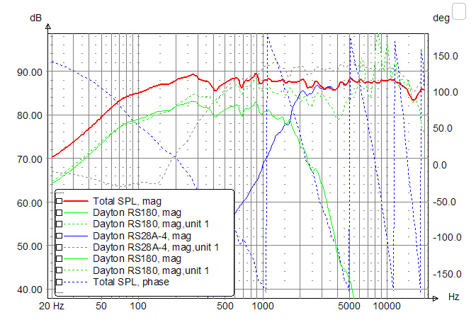
Natalie P SPL curve looks something like this, as published:

NataliePSPL.jpg


We can see down till about 45dB below base SPL, but can't see below this. So, looking at the green midbass curve here, we know that the resonant peaks have been cut by at least about 40dB (flat portion at about 80dB, bottom of the graph is about 40dB) but we don't know whether they've been cut by 60dB, which I had set as a personal minimum target. Even a cut of 40dB is actually excellent, if compared to all those dozens of DIY attempts using LR4 at 2.5KHz with similar drivers.

I then looked at the 
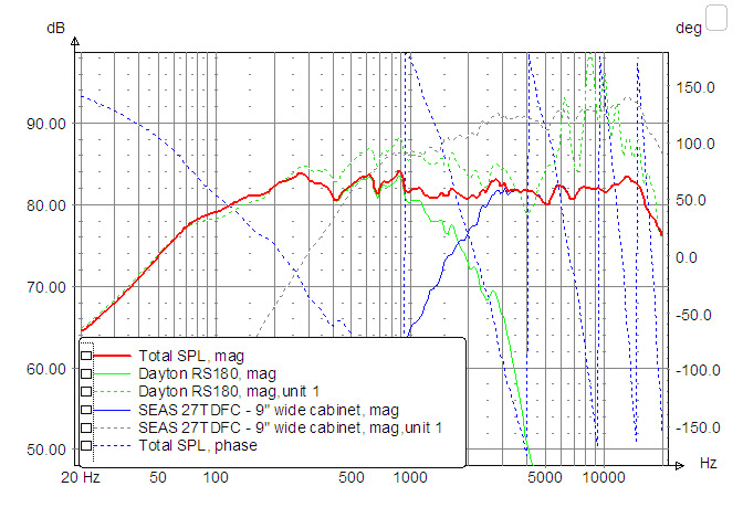
RS 180 Modula MT curves. This is a design done to a tighter budget, trying to get as much out of the excellent drivers as possible.

EM72RS180SPLMag.jpg


Here we are able to see only about 35dB below the base SPL, so we don't know whether the resonant peaks are at -37dB or at -60dB. Till I can see that, I can't quite figure out how effective these midbass filters have been.

One option, of course, would be to pick up Jon Marsh' FRD and ZMA files, put them into a crossover model replicating his design, and see for myself. Jon has often shared his FRD / ZMA files with others -- he's a fabulous guide and mentor that way.

So, I went further afield and looked at one of the most famous DIY designs using expensive metal-cone midbass units: the glamorous Seas Thor kit, which retails for USD 1,900 for a stereo set of drivers and crossovers. This design is by the Great Jo D'Appolito, and needless to say, they are an MTM design. There have been criticisms of his crossover design, and I believe there are many attempts on diyaudio.com to re-design a better crossover with the same enclosure and drivers.

Here's the raw SPL of the very expensive Seas Excel W18 midbass, from their datasheet:

2meub14.png


Nothing surprising here: it's as nasty as any other high-end metal-cone midbass unit. That peak at about 4.8K or so is one of the ugliest in the industry.

This is the only information you get from Seas about the resulting crossover SPL:

4hci6u.png


I was stumped to see that the curves of the individual drivers were missing. Looking at a summed SPL curve does not tell you anything about how much coloration is being added by individual drivers 20-30dB below the base line. And with metal-cone drivers, if I don't have that data, I have absolutely no idea how effective the crossover has been. In short, this summed graph is for lay buyers who want to trust the big brand and high price.

So, in frustration I looked at the crossover diagram for more details:

jaibzo.png


and I couldn't believe my eyes. The midbass crossover is using a simple first-order electrical low-pass (L1), plus a notch (L2/C1/R1). I have very little doubt that the 5K-and-above range has not been cut sufficiently at all. I cannot believe how anyone who knows anything about crossover design will accept this crossover. We are all certain that Dr D'Appolito knows a lot about speaker design -- I suspect he agreed to this crossover due to budget constraints.

This is the kind of design, with fundamental flaws, which get the subjectivist camp of audiophiles all excited. They start tweaking all sorts of things, from capacitor brands to inductor brands to silver-plated internal wirings. Needless to say, some of these things will make audible changes, and some changes will be "better sounding" than others. But none of these changes will make a "flawed" speaker "good". Fundamental flaws must be fixed where they stand, not by changing their surroundings.

I remember one comment from a friend when I was prototyping my very first Asawari a decade back. I found the sound harsh and edgy. My friend said "replace all your white-coffin resistors with non-inductive Mills resistors -- Mills resistors sound very smooth. I can guarantee that this will fix it." Luckily, I had less money and more brains. I stared at the SPL curves, saw that there was a 1-1.5dB hump in the tweeter response, cut that down by tweaking the shunt resistors, and the harshness was gone. My friend has remained my very dear friend, but we have differences in perspective.

We have all heard comments like "This speaker is good for vocals and jazz, but sounds too bright for hard rock", or "That model is superb for hard rock, but soft vocals sound lacking in detail." These remarks are attempts by frustrated listeners to justify flawed designs. Other than bass response, two speakers should aim to sound identical, if flaws are removed. I don't understand what some designers claim to do by "voicing" their designs, other than "voicing" for bass (which has a lot of room dependence and needs careful tuning for optimal performance). In the mids and highs, how can two voicings be both correct? The job of a speaker, IMHO, is accurate reproduction, not "voiced" reproduction. No one will buy a fountain pen if its designer says "This pen is good for writing romantic poetry; we have another model for writing scientific papers." I would laugh at such a remark. I am sometimes afraid that some of my subjectivist audiophile friends would nod sagely and agree with the designer. As you can guess, I don't have too many audiophile friends. :(

The only reasons why speaker designers may tolerate flaws in their speakers are: (i) material science and mechanical engineering hasn't reached the level needed to eliminate fundamental flaws, e.g. cone breakup, and (ii) budget constraints which prevent designing large/complex (i.e. expensive) crossovers or enclosures. These are understandable reasons. But a lot of designs are flawed even before hitting these limits, IMHO. In particular, DIYers sometimes spend money on $300 individual drivers and and then use stupid crossovers. It's very interesting to read all those comments on htguide.com from readers who have criticised Jon Marsh for the high parts cost of his Modula MTM crossover. These same readers will usually have absolutely no comment if someone builds a Seas Thor, which now appears to be a silly and overpriced design. If I had to bet, I'll bet $1,000 of my hard-earned money that the Modula MTM in a good enclosure will perform better overall than the Seas Thor.


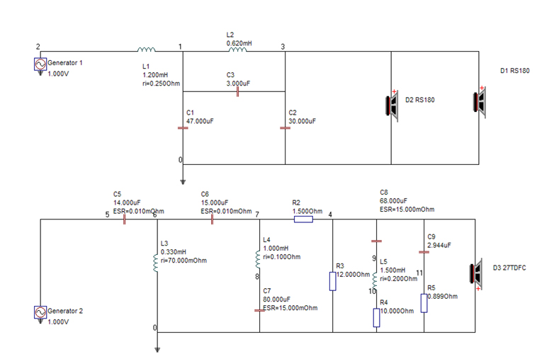
I have now "copied" Jon Marsh' CE crossover (from the Modula MTM) into my modeling software and am trying to see if I can tweak it to fit other drivers. Once I learn to tweak a CE crossover, I'll be able to tackle any projects which involve this class of drivers, and I am 100% certain that any Thor built with such a crossover will beat the original design by miles. This is what the original looks like:

ModulaIVMTMSchm.jpg


Wish me luck. :lol: The next post, whenever it happens, will document what I have been able to do, with Angshu's help, about taming the CE filter.

Edit:
Interestingly, my poking around in old threads found a lot of concern on other forums about the Thor crossover. I found one thread on htguide.com which resulted in a redesign of the entire crossover.

The new xo topology 
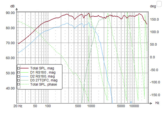
(see here) has a much higher parts count than the original one, and the SPL curves (this post) clearly show how steeply the midbass output is being cut and how well the resonant peak region is being suppressed. The designer has cut the 4.8KHz peak by about 60dB. He's used a CE low-pass for the midbass and what appears to be a 4th order electric on the tweeter. He's also shifted the Fc down to a lower frequency (shift by almost 1KHz, in fact, IIRC) to give his midbass low-pass more space to suppress the 4KHz and higher regions.

These went to confirm my fears that I'm not barking up a fantasy tree -- these are genuine areas of concern.
 
Last edited by a moderator:
For excellent sound that won't break the bank, the 5 Star Award Winning Wharfedale Diamond 12.1 Bookshelf Speakers is the one to consider!
Back
Top