You are using an out of date browser. It may not display this or other websites correctly.
You should upgrade or use an alternative browser.
You should upgrade or use an alternative browser.
Jean Hiraga ( Super - 30 ) Class A - New Enclosure, A Bulky Bank and little modified PCB
- Thread starter sadik
- Start date
Thanks for the update. The amp looks gorgeous. How did you make the top plate vents? I'm also looking for ideas for my upcoming class a amp.
They are cutted on laser cnc machine.
Its huge man will come soon to hear this beauties
Sure Bro... Just confirm me the dates.
Your amp has come out very well, Sadik ji. I must listen to it on my next visit to Vadodara. Which transistors are you using in the output stages?
Sure Sir, Just confirm me the dates. The outputs are NJW0281 & NJW0302 one of the beset sounding Transistors.
Excellent!! Great job, Sadik. Hope to see and hear it someday.
Looks excellent..
Would love to hear it play in a stereo rug someday...
Sure Brothers & Friends You all are welcomed for audition of this amplifier.
I thank you all my friends for the appreciation & nice comments received from you all. This is what keeps the DIY spirit alive within me. Thank you all Again.
Sadik
M
mpw
Guest
Looks excellent..
Would love tobhe
Sadik
Please PM me your address in Baroda
I visit baroda sometimes on work
thanks
mpw
Would love tobhe
Sure Brothers & Friends You all are welcomed for audition of this amplifier.
Sadik
Please PM me your address in Baroda
I visit baroda sometimes on work
thanks
mpw
Thanks a lot.Sure Sir, Just confirm me the dates. The outputs are NJW0281 & NJW0302 one of the beset sounding Transistors.
Do you have to match the transistors? If so, multiple pairs should be purchased to get a good match.
Last edited by a moderator:
Do you have to match the transistors? If so, multiple pairs should be purchased to get a good match.
Not necessary to match. But if you match them it will be benificial.
Professori
Member
Sorry I have been missing the action here for some time...
Very happy to see the fantastic conclusion!
Congrats on the successful and unique build, Sadik-ji! Hope you're climbing the steps slowly to Seventh Heaven...Audio Nirvana!!
What about making your PCB available? Of course, I am interested. Do send mail when free.
Warm regards,
--UKP
Very happy to see the fantastic conclusion!
Congrats on the successful and unique build, Sadik-ji! Hope you're climbing the steps slowly to Seventh Heaven...Audio Nirvana!!
What about making your PCB available? Of course, I am interested. Do send mail when free.
Warm regards,
--UKP
Wow..what a lovely build. Absolutely gorgeous Mr.sadik. You are a designer and master crafter par excellence. Salutations
Okay...iam off to get a towel to wipe my drool off my shirt now
Thank You @newlash09
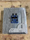
The wheel of update should keep on running, so here is some update on my another Jean Hiraga 30 Watt Class A amplifier. This amplifier has a PCB from Jims Audio with Kubuta regulator. Below is the photo of same.
The Heat Sink is 350 mm Height, and 300 mm weight, A massive 10 Kg each x 2 Nos for left and right.
The Power Bank.
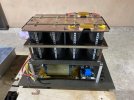
Each Capacitor is 1,50,000 uf / 50 volts x 8 Nos a total of 12,00,000 uf (twelve lac micro farad) capacitance with a massive 800 VA transformer ( 25-0-25 AC / 800 VA). The top copper plates (+ve rail, -ve rail and ground) are 5 mm thick which are also cutted on water jet. I am following a star ground in this power supply. Below is the layout how i arranged the power supply. (The total weight of this Power Supply along with R Core transformer is approx 20 Kg)
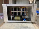
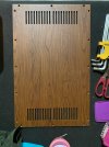
The Enclosure is made from Aluminum, The side walls left and right are the heat-sink itself and rest 4 sides Top, Bottom, Front and Back are 4 mm thick aluminum sheets cutted on CNC laser cutting machine.
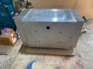
This time i went with an unique look for my enclosure, i selected wood finish on Aluminum. just have a look below, its 4 mm thick aluminum plate.
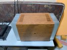
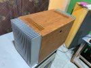
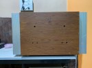
And the final look, The connectors are yet to be mounted (I will upload another photos after mounting & wiring the connectors)
The modules are tested and amp is dead silent. The sound of this amplifier do not need any description / introduction, the Jean Hiraga owners know the tonal signature of this amp. And that is the only reason, I am making this amp for the 3rd time. Each time I have upgraded the Power Supply Bank. The bulky bank helps in getting the exact low end notes with much intensity (one can call tight & punchy low end) which i was missing with my earlier power supply bank as well as capacitance multiplier (I have used cap multiplier in my first built). The Capacitance multiplier and low capacitance bank works good only in mid and highs region, It dose not gives the refined tone for the Bass (the bass is loose), When compared the Bass of actual capacitance bank with cap multiplier or low capacitance bank, one can easily make out the difference in tightness / tonal character of Bass. The bass with such a huge capacitance bank is really on another level.
Right now the initial bias is 1.2 Amp, and i think after a stable temperature this should be around 1.5 to 1.6 amp. Too much of heat and the heatsinks are already an overkill to take care of this temperature. I will update the readings of temperature as well as bias current after few days of monitoring my amplifier.

The Heat Sink is 350 mm Height, and 300 mm weight, A massive 10 Kg each x 2 Nos for left and right.
The Power Bank.
Each Capacitor is 1,50,000 uf / 50 volts x 8 Nos a total of 12,00,000 uf (twelve lac micro farad) capacitance with a massive 800 VA transformer ( 25-0-25 AC / 800 VA). The top copper plates (+ve rail, -ve rail and ground) are 5 mm thick which are also cutted on water jet. I am following a star ground in this power supply. Below is the layout how i arranged the power supply. (The total weight of this Power Supply along with R Core transformer is approx 20 Kg)

The Enclosure is made from Aluminum, The side walls left and right are the heat-sink itself and rest 4 sides Top, Bottom, Front and Back are 4 mm thick aluminum sheets cutted on CNC laser cutting machine.


This time i went with an unique look for my enclosure, i selected wood finish on Aluminum. just have a look below, its 4 mm thick aluminum plate.

And the final look, The connectors are yet to be mounted (I will upload another photos after mounting & wiring the connectors)


The modules are tested and amp is dead silent. The sound of this amplifier do not need any description / introduction, the Jean Hiraga owners know the tonal signature of this amp. And that is the only reason, I am making this amp for the 3rd time. Each time I have upgraded the Power Supply Bank. The bulky bank helps in getting the exact low end notes with much intensity (one can call tight & punchy low end) which i was missing with my earlier power supply bank as well as capacitance multiplier (I have used cap multiplier in my first built). The Capacitance multiplier and low capacitance bank works good only in mid and highs region, It dose not gives the refined tone for the Bass (the bass is loose), When compared the Bass of actual capacitance bank with cap multiplier or low capacitance bank, one can easily make out the difference in tightness / tonal character of Bass. The bass with such a huge capacitance bank is really on another level.
Right now the initial bias is 1.2 Amp, and i think after a stable temperature this should be around 1.5 to 1.6 amp. Too much of heat and the heatsinks are already an overkill to take care of this temperature. I will update the readings of temperature as well as bias current after few days of monitoring my amplifier.
amrutmhatre90
Well-Known Member
This thing is a tank!!!
Superb job, I used to read this thread but without pictures. Love the wooden aesthetics on this, may I know why not some people use real wood ? any issues? cause I had seen some amps with only heat sinks and back plate as metal parts on the chassis.
Would love to know the temperatures this goes to.
Impressive work, too good.
The wheel of update should keep on running, so here is some update on my another Jean Hiraga 30 Watt Class A amplifier. This amplifier has a PCB from Jims Audio with Kubuta regulator. Below is the photo of same.
View attachment 66864
The Heat Sink is 350 mm Height, and 300 mm weight, A massive 10 Kg each x 2 Nos for left and right.
The Power Bank.
Each Capacitor is 1,50,000 uf / 50 volts x 8 Nos a total of 12,00,000 uf (twelve lac micro farad) capacitance with a massive 800 VA transformer ( 25-0-25 AC / 800 VA). The top copper plates (+ve rail, -ve rail and ground) are 5 mm thick which are also cutted on water jet. I am following a star ground in this power supply. Below is the layout how i arranged the power supply. (The total weight of this Power Supply along with R Core transformer is approx 20 Kg)
View attachment 66865
The Enclosure is made from Aluminum, The side walls left and right are the heat-sink itself and rest 4 sides Top, Bottom, Front and Back are 4 mm thick aluminum sheets cutted on CNC laser cutting machine.
View attachment 66866
View attachment 66867
This time i went with an unique look for my enclosure, i selected wood finish on Aluminum. just have a look below, its 4 mm thick aluminum plate.
View attachment 66868
And the final look, The connectors are yet to be mounted (I will upload another photos after mounting & wiring the connectors)
View attachment 66871
View attachment 66870
View attachment 66869
The modules are tested and amp is dead silent. The sound of this amplifier do not need any description / introduction, the Jean Hiraga owners know the tonal signature of this amp. And that is the only reason, I am making this amp for the 3rd time. Each time I have upgraded the Power Supply Bank. The bulky bank helps in getting the exact low end notes with much intensity (one can call tight & punchy low end) which i was missing with my earlier power supply bank as well as capacitance multiplier (I have used cap multiplier in my first built). The Capacitance multiplier and low capacitance bank works good only in mid and highs region, It dose not gives the refined tone for the Bass (the bass is loose), When compared the Bass of actual capacitance bank with cap multiplier or low capacitance bank, one can easily make out the difference in tightness / tonal character of Bass. The bass with such a huge capacitance bank is really on another level.
Right now the initial bias is 1.2 Amp, and i think after a stable temperature this should be around 1.5 to 1.6 amp. Too much of heat and the heatsinks are already an overkill to take care of this temperature. I will update the readings of temperature as well as bias current after few days of monitoring my amplifier.
What ton of AC required in room bhai?The wheel of update should keep on running, so here is some update on my another Jean Hiraga 30 Watt Class A amplifier. This amplifier has a PCB from Jims Audio with Kubuta regulator. Below is the photo of same.
View attachment 66864
The Heat Sink is 350 mm Height, and 300 mm weight, A massive 10 Kg each x 2 Nos for left and right.
The Power Bank.
Each Capacitor is 1,50,000 uf / 50 volts x 8 Nos a total of 12,00,000 uf (twelve lac micro farad) capacitance with a massive 800 VA transformer ( 25-0-25 AC / 800 VA). The top copper plates (+ve rail, -ve rail and ground) are 5 mm thick which are also cutted on water jet. I am following a star ground in this power supply. Below is the layout how i arranged the power supply. (The total weight of this Power Supply along with R Core transformer is approx 20 Kg)
View attachment 66865
The Enclosure is made from Aluminum, The side walls left and right are the heat-sink itself and rest 4 sides Top, Bottom, Front and Back are 4 mm thick aluminum sheets cutted on CNC laser cutting machine.
View attachment 66866
View attachment 66867
This time i went with an unique look for my enclosure, i selected wood finish on Aluminum. just have a look below, its 4 mm thick aluminum plate.
View attachment 66868
And the final look, The connectors are yet to be mounted (I will upload another photos after mounting & wiring the connectors)
View attachment 66871
View attachment 66870
View attachment 66869
The modules are tested and amp is dead silent. The sound of this amplifier do not need any description / introduction, the Jean Hiraga owners know the tonal signature of this amp. And that is the only reason, I am making this amp for the 3rd time. Each time I have upgraded the Power Supply Bank. The bulky bank helps in getting the exact low end notes with much intensity (one can call tight & punchy low end) which i was missing with my earlier power supply bank as well as capacitance multiplier (I have used cap multiplier in my first built). The Capacitance multiplier and low capacitance bank works good only in mid and highs region, It dose not gives the refined tone for the Bass (the bass is loose), When compared the Bass of actual capacitance bank with cap multiplier or low capacitance bank, one can easily make out the difference in tightness / tonal character of Bass. The bass with such a huge capacitance bank is really on another level.
Right now the initial bias is 1.2 Amp, and i think after a stable temperature this should be around 1.5 to 1.6 amp. Too much of heat and the heatsinks are already an overkill to take care of this temperature. I will update the readings of temperature as well as bias current after few days of monitoring my amplifier.
surfatwork
Well-Known Member
Best to tell them to upgrade the electricity transformer near your house.
keith_correa
Well-Known Member
Powder coating? I think the process is called sublimation.Excellent finish and look @sadik
How does one go about getting the wood finish on aluminum?
Cheers,
Raghu
No need in present atmospheric conditions, and i think the heat sinks i have used are still an overkillWhat ton of AC required in room bhai?
lolBest to tell them to upgrade the electricity transformer near your house.
This 30 watt Amp can easily outperform 150 to 180 watt class AB amplifier. Even a 20 Watt class A amplifier will outperform 120 watt class AB amplifier.@sadik , not very conversant about power ratings. Would this 30W Class A be more powerful than a 120 watt per channel (at 8 ohm ) Class AB amp ?
Thankyou @Hiten This process is somewhat like powder coating.Excellent work Sadik !
Is wood finish aluminum panel composite material and laser or cnc cut ?
regards.
Thanks @raghupb Its a process somewhat similar to powder coating.Excellent finish and look @sadik
How does one go about getting the wood finish on aluminum?
Cheers,
Raghu
No its not sublimation. As i said above its similar to powder coating.Powder coating? I think the process is called sublimation.
amrutmhatre90
Well-Known Member
None of the images are available now. All lost ? Or am i the only one having issue with this.
Not only you, its for all.
Only latest images are available
All of the old images are lost, only new images can be viewedNone of the images are available now. All lost ? Or am i the only one having issue with this.
Check out our special offers on Stereo Package & Bundles for all budget types.
Similar threads
- Replies
- 14
- Views
- 13K
- Replies
- 35
- Views
- 9K

