You are using an out of date browser. It may not display this or other websites correctly.
You should upgrade or use an alternative browser.
You should upgrade or use an alternative browser.
Tripath TA2022 based class T 100+100W DIY stereo amp
- Thread starter omishra
- Start date
sachu888
Well-Known Member
Please share the total cost if possible.
Regards,
Sachin
Regards,
Sachin
avidyarthy
Well-Known Member
The enclosure looks classy !!!!!
vivek.saikia
Active Member
Thanks Om for sharing the pictures. I was rather waiting for them.
Could you please share more pictures of the innards and share info regarding the sources from where you procured the components and the respective itemized price breakup.
For picture sharing, you can upload your pictures in picassa or imageshack.us and share the links here.
Could you please share more pictures of the innards and share info regarding the sources from where you procured the components and the respective itemized price breakup.
For picture sharing, you can upload your pictures in picassa or imageshack.us and share the links here.
Its Tripath TA2022 based class-T amplifier from 41Hz dot com - amp1.
I added control circuit for speaker protection which utilizes chip output for over temperature, over current, over/under supply voltage. I put auto muting on on/off, slow start and DC protections from my side.
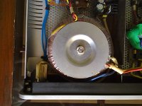
Toroidal transformer is from Miracle, Bangalore 22-0-22,225VA
I removed shielded cable from input RCA to amp board and added twisted pair for less capacitance. Put ferrite bid on input and output wires to avoid EMI leakage outside cabinet.
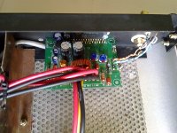
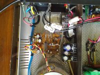
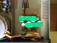
View attachment 4741
View attachment 4742
Last edited:
Please share the total cost if possible.
Regards,
Sachin
It cost me like this -
USD 40 for amp1 kit
Rs 3.0K for toroidal transformer
Rs 4.5K for cabinet
Rs 2.5K for PS/wires/connectors/DIY control circuit.
Total approx Rs ~12K
One more thing - that aluminum power switch and all hole are crafted out by me. Aluminum switch knob is cut from bolt of window latch and hand polished.
Do you hear a difference in HF with and without ferrite beads?
They supposedly reduce frequency extension at the top.
--G0bble
These bids are affecting 100KHz onwards and more effectively 1MHz and up. My main concern was the internal modulation frequency of 550KHz-1.2MHz (variable) and its multiple harmonics were affecting to AM/FM radio as noise.
Also from digital sources HF tend to be bright. I thought it may be due to some digital noise coming from source to amp's modulation stage of chip or vice versa.
To overcome this, some people (and Tripath application notes) advice grounding to chassis using small caps of 100pF range at input and 4700kpF at output. It was mellowing down HF. I did not like it and eventually removed them.
So after setting bench mark of 500KHz, I added these beads. and all noises are gone with clarity in sound. Now if you place ear near 1" of speaker still there is no background noise in absence of source - Absolute dark. Earlier it was hiss audible at same distance - 1" from speakers. Now its crystal clear and peaceful. At least effect is towards positive. Did not affect 20KHz but upwards 200KHz. Now AM radio is noise free along with this. (I have world band radio which tunes from 150KHz)
I have using this with Wharfedale Diamond 9.2 with DIY The "Full Frequency Range Cable" using cat 5 cable connected with nakamichi spades and banana plugs at each end.
Last edited:
vivek.saikia
Active Member
That's a really nice piece of DIY amp.
I have one question though. These famous Chinese Topping amps use the same chip and just manage to churn out 7watts of power (@4ohm load). So how come these 41hz chips manages to extract 100watts of power from the same chip? Are they used in the bridged configuration? or is it because of that beefy power supply?
Nicely done omishra,
vivek
this datasheeet says 100W into 4ohms
http://www.datasheetcatalog.org/datasheet/Tripath/mXyzxwwu.pdf
vivek
this datasheeet says 100W into 4ohms
http://www.datasheetcatalog.org/datasheet/Tripath/mXyzxwwu.pdf
Last edited:
vivek.saikia
Active Member
Nicely done omishra,
vivek
this datasheeet says 100W into 4ohms
http://www.datasheetcatalog.org/datasheet/Tripath/mXyzxwwu.pdf
So, what I deduce from the TA2022 datasheet is that more power can be extracted from the Topping amps by carefully changing the voltage and tolerance values of the resisters/capacitors. Is that a correct assumption?
That's a really nice piece of DIY amp.
I have one question though. These famous Chinese Topping amps use the same chip and just manage to churn out 7watts of power (@4ohm load). So how come these 41hz chips manages to extract 100watts of power from the same chip? Are they used in the bridged configuration? or is it because of that beefy power supply?
Thanks again!
It's not bridged, playing in stereo mode. I suspect the Chini Bandhu's
It's max output is dependent on power supply rating. It operates from +-12 to +-40 VDC. I am using it with PS of +-33VDC, approx 6A capacity. So I could drive max ~70Watt/ch in my WF D 9.2 speakers with 6 ohm impedance. Still its huge inside house.
Few things I could say about this layout is -
- Low level signal is away at opposite corner of main power supply.
- Signal paths are not crossing noisy power lines.
- Toroidal transformer, Controller, warning buzzer and speaker protection relay are separated from amp board using metal sheet. See two compartments.
- For controller board, I wound 48+48 turns of 24SWG enameled wire on transformer to get 12-0-12 for relay and other small power requirements.
- Power supply uses two parallel bridge rectifiers and set of caps. This is to minimize diode resistance and less heat dissipation in PS.
- Chassis as heat sink.
- To avoid drilling in Chassis I used that meshed bottom plate (bought for Rs 10 from scrap vendor). It is fixed using 4 bolts of chassis feet itself. So no extra hole at chassis bottom.
Last edited:
I think he might be talking about changing resistors which are used to sense under/over voltage cut. These need to chosen in accordance with PS voltage. These setting are hardwired with some resistor values. For more output more voltage (of course speaker impedance matters) will be required within limits of chip. My amp planned for +-33V mutes at below 27V and above 34V. same thing will be different for using it at +-40V.Vivek
I am not sure how can you exceed the power rating of the chip by changing the resistors/caps
Thanks again!
It's not bridged, playing in stereo mode. I suspect the Chini Bandhu's
It's max output is dependent on power supply rating. It operates from +-12 to +-40 VDC. I am using it with PS of +-33VDC, approx 6A capacity. So I could drive max ~70Watt/ch in my WF D 9.2 speakers with 6 ohm impedance. Still its huge inside house.
Few things I could say about this layout is -
- Low level signal is away at opposite corner of main power supply.
- Signal paths are not crossing noisy power lines.
- Toroidal transformer, Controller, warning buzzer and speaker protection relay are separated from amp board using metal sheet. See two compartments.
- For controller board, I wound 48+48 turns of 24SWG enameled wire on transformer to get 12-0-12 for relay and other small power requirements.
- Power supply uses two parallel bridge rectifiers and set of caps. This is to minimize diode resistance and less heat dissipation in PS.
- Chassis as heat sink.
- To avoid drilling in Chassis I used that meshed bottom plate (bought for Rs 10 from scrap vendor). It is fixed using 4 bolts of chassis feet itself. So no extra hole at chassis bottom.
Your chassis layout complements the good board design. A really good piece of DIY. I like the idea of the meshed bottom plate and am planning to implement it in my current project. Thanks for the pictures. Well done.:clapping:
gopib
vivek.saikia
Active Member
Vivek
I am not sure how can you exceed the power rating of the chip by changing the resistors/caps
if you want more than 100w then go for bridge , but only 8ohm load, it can give 150w
Hey Borg, I think you got me wrong here. I was talking about increasing the power output of the Topping amps (like these) by increasing the power supply voltage and current and then changing the resisters and capacitors to handle the additional voltage/current. But seems I was the one who got confused between TA2022 and TA2024. Topping indeed makes amps with the TA2022 chip with 80watt output and they have another amp using TA2024 which outputs just 7watts.
There are the two different amps from Topping using these two chips:
Topping TP10 Mark4 Digital Amplifier Class T Amp TA2024 | eBay
TOPPING TP60 TP-60 & TA2022 T-Amp & 2X80W & STEREO AMP | eBay
Cheers!
I think he might be talking about changing resistors which are used to sense under/over voltage cut. These need to chosen in accordance with PS voltage. These setting are hardwired with some resistor values. For more output more voltage (of course speaker impedance matters) will be required within limits of chip. My amp planned for +-33V mutes at below 27V and above 34V. same thing will be different for using it at +-40V.
this makes sense
+1, truly a class act. And the volume knob is made by you too....Kudos!!The enclosure looks classy !!!!!
Wharfedale Linton Heritage Speakers in Walnut finish at a Special Offer Price. BUY now before the price increase.
Similar threads
- Replies
- 22
- Views
- 6K


