Guidance with protecting my gears

:D :D :D
Silver is nothing. Here in India you put copper strips for lightning rod conductor it gets stolen. The conductor for earth gets stolen ASAP. At Chennai Citibank Data Center, stealing of the copper earthing strip used to be the most pilfered item.
With the current rates of aluminium, even aluminium isn't safe I guess.
That incident was at Vishakapatnam aka Vizag. One power contactor had something like half a kilo silver said my colleague who worked there. I was coordinating the supply chain.

Pilferage is not a new thing. We used to loose even 25mm MS rod buried in ground for earth grid. We lost 4km aluminium conductor when we were ready to energize a 400kV line in 1991. Imagine climbing up 25-30m on towers and cutting down them that are hanging on 2m long insulators!!! Data centers are easy access that way.

Anyways off topic
 
We can't have a separate generating station with a hyper performance parameters of primary response time of 0.05 cycles (1ms) and zero impedance connected with super conductors for the audio gear so that all transient response and steady states are preserved.

We power engineers love some impedance so that if you have a short circuit in your mixie or fan or lamp you won't get thousands of amperes flowing in to burn down everything behind before a protection device can operate and isolates the fault..

Highest fault rating generally is 50kA for 3 sec in Low Voltage 415V while at high voltage generally it is 63kA OR 40kA for 1 sec at 400kV. Your household distribution boards may melt and vapourize at 10kA or so.

Can't have zero impedance networks - short circuit means infinite current!!!

Yes, UPS and such inverters introduce harmonics due to the working principles behind them. Carefully designed power / isolation transformers could remove these disturbances.

Even if you don't use a UPS, your neighbor who is connected to the same network or even your mobile chargers, LED lights, a/cs with inverter control, and computer power supplies will be injecting harmonics into the system. These will result in distortion of voltage wave form that present to your audio's power input and create harmonics into your audio too. A harmonic voltage will cause similar current in the load unless you can identify it and take measures to neutralize it.

Live with it...
IME, all of this mentioned above is imagination related to noise in power lines. The seller of these power smoothing equipment exaggerats the noise and hype them over proportion to sell their products. I have many times in the past measured my line AC on an oscilloscope in my home and have always got a perfect sine wave without any noise. But if you see the catalogues of these companies they always show plenty of noise which may not be true. YMMV.
 
IME, all of this mentioned above is imagination related to noise in power lines. The seller of these power smoothing equipment exaggerats the noise and hype them over proportion to sell their products. I have many times in the past measured my line AC on an oscilloscope in my home and have always got a perfect sine wave without any noise. But if you see the catalogues of these companies they always show plenty of noise which may not be true. YMMV.
If you have perfect sine wave that is wonderful.

I don't believe in vendors or catalogue or imagine things. I am a practicing power engineer since 1990 though now working in a regulator office , specifying operating parameters, preparing electricity codes, monitoring performance of power system operators, analysing power system incidents etc.etc.

We don't have oscilloscope or such mundane instruments but current and voltage transformers of 0.2% and Power Quality Analysers, measurement and decoding softwares etc.that costs a few Cr.and analyse these reports as per IEEE 1159 or IEC 60001.

If we shouldn't quote these I have nothing to say.

Power systems worldwide need not invest crores and crores for harmonic filters, SVC, capacitor banks, Wide Area Monitoring systems etc.etc. and go back 50 years.
Can you let me know a simple thing - how to listen and decode if my power supply is noisy. I am not talking about hum or hiss but a clean sounding amplifier? I am curious to know and learn.
 
Off topic. But thought I would share. I recently changed my miniature circuit breaker which was feeding my dedicated audio line which has been taken from the meter room on the ground floor to my apartment on the 5th floor. My circuit breaker was more than 20 years old and the contacts had slightly rusted. I live near the sea so that must have hastened the corrosion. I changed to a new Siemens one. Sound has improved a wee bit. FWIW, Siemens uses silver plated contacts in all its circuit breakers. It’s their standard. Their logic is it has the least resistance and even when it oxidises, resistance increase is minimal. For them least resistance is very important since it’s a breaker and hence a safety device.
 
'Power-supply sniffer', FWIW. :D
 

Attachments

  • how-to-check-your-power-supply-for-noise.pdf
    115.7 KB · Views: 16
Last edited:
Off topic. But thought I would share. I recently changed my miniature circuit breaker which was feeding my dedicated audio line which has been taken from the meter room on the ground floor to my apartment on the 5th floor. My circuit breaker was more than 20 years old and the contacts had slightly rusted. I live near the sea so that must have hastened the corrosion. I changed to a new Siemens one. Sound has improved a wee bit. FWIW, Siemens uses silver plated contacts in all its circuit breakers. It’s their standard. Their logic is it has the least resistance and even when it oxidises, resistance increase is minimal. For them least resistance is very important since it’s a breaker and hence a safety device.
All electrical equipment under go several kinds of stresses. Electromagnetic, mechanical, environment, etc.

Circuit breakers have a life depending on the duty / switching cycle they are subject to.Even using a breaker not designed for inductive duty cycle to switch motors can hasten damage to contact. Or if you don't switch often but overloading a wee bit can result in the neutral terminal to overheat due to Peltier effect and ultimately burn.

In your case the environment, perhaps the rating, loading /overloading etc.must have accelerated the pitting resulting in contact chatter that causes flicker that bare eyes cannot detect. But electrical devices can get affected that you may have manifested in your audio.

The contact resistance of low voltage breakers are in the microohm or a few milli ohm range. Siemens, ABB, Schneider, Havells or any one have to meet IEC or national standards to get qualified in type tests. They all use silver plated contacts to lower contact resistance

A few milli ohm increase from original micro ohm range or lower milli ohm ranges cannot manifest in detectable voltage drops in your audio line drawing maybe 10A max. Ohm's law.
 
Last edited:
All electrical equipment under go several kinds of stresses. Electromagnetic, mechanical, environment, etc.

Circuit breakers have a life depending on the duty / switching cycle they are subject to.Even using a breaker not designed for inductive duty cycle to switch motors can hasten damage to contact. Or if you don't switch often but overloading a wee bit can result in the neutral terminal to overheat due to Peltier effect and ultimately burn.

In your case the environment, perhaps the rating, loading /overloading etc.must have accelerated the pitting resulting in contact chatter that causes flicker that bare eyes cannot detect. But electrical devices can get affected that you may have manifested in your audio.

The contact resistance of low voltage breakers are in the microohm or a few milli ohm range. Siemens, ABB, Schneider, Havells or any one have to meet IEC or national standards to get qualified in type tests. They all use silver plated contacts to lower contact resistance

A few milli ohm increase from original micro ohm range or lower milli ohm ranges cannot manifest in detectable voltage drops in your audio line drawing maybe 10A max. Ohm's law.
I have a hunch that the loose contacts on the input side or increase of impedance on the input side have a drastic detrimental effect on valve amps than on step-down voltage supplies that solid state amps use.

Even a few voltage drop across these loose contacts or across the increased impedance caused by adding voltage stabilizer causes a marginal drop on the secondary windings of step-down transformers, but have a direct impact on valve amps using the mains voltage after rectification. And if one is using a regulated power supply in solid state amps, the effect will not be felt at all.

But valve amps using high voltages, will have 1:1414 drop in the voltage or even more if it has a transformer stepping up the voltage.
TBH, I did not understand what you are trying to convey. Why would anyone built an amplifier with loose connection at the first place.
 
TBH, I did not understand what you are trying to convey. Why would anyone built an amplifier with loose connection at the first place.
loose connection on the mains voltage connection like in the case of @prem, the circuit breaker developed loose contact.
 
loose connection on the mains voltage connection like in the case of @prem, the circuit breaker developed loose contact.
Oh, yeah these loose connections lead to voltage drops, heating, further loose contacts, sparking, melting and ultimately a fire. This is what happens in most electrical fires.

Check the distribution boards once in a while if you can to make sure all screws and connections are tight. If possible dab a little silicone grease to prevent corrosion. "Exercise" the breakers (MCBs / MCCBs) once in a year to ensure they work. It is generally recommended to trip the RCCB / ELCB with the manual push button again once a year.

Electrons are friends doing your work faithfully if they are treated properly else they are the worst enemies ;) ;)

I have a hunch that the loose contacts on the input side or increase of impedance on the input side have a drastic detrimental effect on valve amps than on step-down voltage supplies that solid state amps use.

Even a few voltage drop across these loose contacts or across the increased impedance caused by adding voltage stabilizer causes a marginal drop on the secondary windings of step-down transformers, but have a direct impact on valve amps using the mains voltage after rectification. And if one is using a regulated power supply in solid state amps, the effect will not be felt at all.

But valve amps using high voltages, will have 1:1414 drop in the voltage or even more if it has a transformer stepping up the voltage.
Very, true... for a 240/300V step up trafo, a drop of 10V in main @240V, it is a 12.5V drop at the power supply rails. While for a solid state equipment with regulated power it may not be a big issue since it steps down.

After all these puny transformers do not have the kind of design, materials and rigorous type tests that the transformers in power system undergo. Losses in power system are huge so a small saving could save building another generating unit or even a power station
 
Maybe get a Fluke 435 ... $5000
I think you did not understand my question. I am asking how do you "LISTTEN" to a noisy power supply other than hums and hisses which anyway wont be there in any decent setup. Even if i measure the noise using this fluke and if i can't listen them - its as good as non-existing for me. Other way round if i cannot measure the noise - but can hear the noise - for me the noise exist. Doesn't really matter if i can measure them or not.
 
loose connection on the mains voltage connection like in the case of @prem, the circuit breaker developed loose contact.
That cannot be generalized. If its that loose a connection, the MCB would have tripped. Contact resistance will be there everywhere, even in your soldering, but that does not mean noise is generated due to that.
 
That cannot be generalized. If its that loose a connection, the MCB would have tripped. Contact resistance will be there everywhere, even in your soldering, but that does not mean noise is generated due to that.
The basics of MCB is, it will trip for a fault or short circuit downstream not for open circuits. It works with a thermal trigger for overloads and magnetic trigger for shorts.

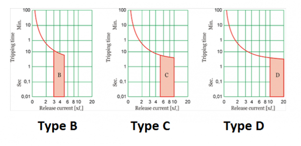
types-of-MCB-tripping-curve.png
Usually in residential building, Type C is used. Thermal trigger is up to around 6 times the rating and thereafter magnetic trigger.

MCB will not trip for a loose contact unless it results is a short circuit and current about 3 times the rating of it.

A loose contact will generate sparks (contact chatter) and EMIs, flickers that one may not be able to detect with naked eyes unless it is prolonged. Please look for ENA P28 standard to understand it.
 
The basics of MCB is, it will trip for a fault or short circuit downstream not for open circuits. It works with a thermal trigger for overloads and magnetic trigger for shorts.

View attachment 69435
Usually in residential building, Type C is used. Thermal trigger is up to around 6 times the rating and thereafter magnetic trigger.

MCB will not trip for a loose contact unless it results is a short circuit and current about 3 times the rating of it.

A loose contact will generate sparks (contact chatter) and EMIs, flickers that one may not be able to detect with naked eyes unless it is prolonged. Please look for ENA P28 standard to understand it.
Back to my question - How do you ' LISTEN' to loose contact in your electrical wiring?
 
Back to my question - How do you ' LISTEN' to loose contact in your electrical wiring?
Use all your senses direct on the wiring or wiring accessories not listen through an amp. At least I won't depend on an amp.

Or if you insist of listening to noise use the good old MW radio tuned to a frequency with no station. More to read in the link below

Hearing - chr-chr, pht-pht in your switches, sockets etc., buzzing sounds
Sight - carbon marks, discolored wires or switches or plugs or sockets, sparks when switching, flicker of lights
Smell - burning smell of insulation or melting metal
touch - hot switches, sockets that you handle everyday

I could save my kitchen burning down when I heard some strange sound while switching an induction cooker, promptly changed the burning socket and plug - just 2A overload over the rating of the plug and socket.

a video may explain in detail


A beautiful, well-constructed speaker with class-leading soundstage, imaging and bass that is fast, deep, and precise.
Back
Top